


27
WARNING
Once the high and low fire have been set, be sure
the press the Function key to end high fire mode.
The middle LED light, L2, will stop flashing when
high fire mode is off.
NOTE
Step 5-7 are for adjusting the discharge air setting.
The discharge air temperature setting is factory set
to the recommended 70ºF. Only adjust the setting if
needed.
NOTE
After modifying a setting, the Enter key must be
pressed to save the change. If the Enter key is not
pressed the display will return to the setpoints menu
without saving the change.
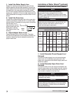
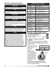
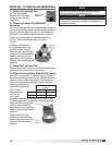
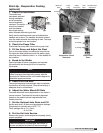
Eight Stage Manifold
Pressure (in. wg)
Natural Gas LP
Low Fire
7/8 2-1/2
High Fire
3-1/2 10
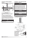
High Fire
Adjustment
Low Fire
Adjustment
High Fire
Terminal
3. Send the Unit to Low Fire
Disconnect and isolate the wire from the high fire
terminal to send the unit to low fire.
4. Check the Low Fire Manifold Pressure
Measure each valve’s low fire manifold pressure.
The recommended low fire manifold pressure is 7/8 in.
wg for natural gas and 2-1/2 in. wg for LP.
If needed, use the low fire adjustment screw on each
staged gas valve to properly set both low manifold
settings. Counterclockwise rotation will decrease the
gas pressure and clockwise rotation will increase the
gas pressure.
When the low fire manifold pressure is properly set,
reattach the disconnected
wire to the high fire
terminal, allow the heat
switch to close
or remove the
jumper.
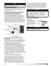
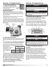
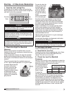
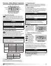
5. Access the Setpoints Menu
Press and hold the Function
key for three seconds to
access the Setpoints Menu.
The display will read “SEt.”
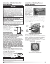
6. Access the Discharge Air
Temperature Setting
Using the Up or Down key, scroll through the
Setpoints Menu until the
display reads “dtS”, then
press the Enter key. The
display will change to the
discharge air temperature
setting.
7. Edit the Setting
Use the Up or Down key to change the discharge
air temperature setting. When the correct setting is
displayed, press the Enter key to save the setting and
return to the Setpoints Menu.
8. Access the Inlet Air Sensor Setting
From the Setpoints Menu, use the Up or Down key to
navigate through the menu options until the display
reads “iAS”. Once the
display reads “iAS”, press
the Enter key. The display
will change to the inlet air
sensor setting.
NOTE
Steps 8 - 9 are provided for adjusting the inlet air
set point. The inlet air sensor is preset to the factory
recommended 65ºF, only adjust if needed.
NOTE
The inlet air sensor monitors the temperature of
the inlet air. If the inlet air is above the sensor’s set
point, the inlet air sensor shuts off the furnace and
continues to supply the warm outside air.
9. Edit the Setting
Use the Up or Down key to change the inlet air setting.
When the correct setting is displayed, press the Enter
key to save the setting and return to the Setpoints
Menu.
NOTE
After modifying a setting, the Enter key must be
pressed to save the change. If the Enter key is not
pressed, the display will return to the Setpoints
Menu without saving the change.
NOTE
Steps 10 - 11 are provided for adjusting the room
override setting. Only adjust the setting if the room
override function is desired.
NOTE
The room override function temporarily changes
the discharge air temperature to the room override
setting if the room thermostat is not satisfied.
®
Model IG / IGX Make-Up Air