


34
NOTE
Steps 6 through 8 are provided to adjust the
minimum cooling temperature. The minimum cooling
is preset to the factory recommended 75ºF (24ºC).
Only adjust if needed.
NOTE
The inlet air sensor function overrides and shuts
down the evaporative cooler if the outside
temperature falls below the minimum cooling
temperature.
8. Exit Program Mode
After ten seconds of idle time the controller will exit
Program Mode.
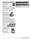
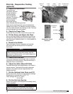
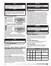
7. Adjust the Minimum Cooling
Temperature
While in the
Program Menu,
use the Up and
Down keys to
navigate the
Menu Options
until “toF” is
displayed. Press the
Enter key to access the selected Menu Option setting.
Use the Up and Down keys to adjust the Minimum
Cooling Temperature as needed. Press the Enter key
to save the Minimum Cooling Temperature setting and
return to the Program Menu.
Minimum Cooling
Temperature Display
NOTE
The Enter key must be pressed to save the new
minimum cooling temperature.
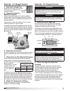
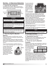
Start-Up - Water Wizard™ (optional)
4. Close Solenoid
With the pressure set, press the Function key
for one second to deactivate Flow Test Mode
and allow the supply solenoid to close.
5. Check Media
Start the cooling cycle and check the media after one
hour of operation. If the media is continuously dry or if
too much water is draining from the sump tank, refer
to Troubleshooting, Water Wizard™.
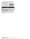
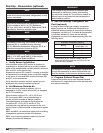
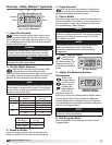
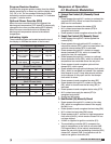
Program Display
6. Enter Program Mode
Press and hold
the Enter key
for three seconds. The
display will read “Pro”
when Program Mode is
active.
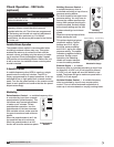
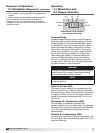
Function
L1 L2 L3
Enter
Up
Down
Water Wizard™ User Interface
Key Function Description
3. Break-In Media
Leave the supply solenoid open to saturate and
break-in media for 20 minutes with the blower off.
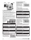
1. Open the Solenoid
Confirm that the manual water supply valve
is closed. Press and hold the Function key
for one second. L3 will begin blinking (short on, long
off), indicating that Flow Test Mode is active and the
supply solenoid is open.
2. Set the Water Pressure
With the solenoid open, set the supply water
pressure to the correct setting from the
following tables. Use the manual supply valve to adjust
the supply pressure. A pressure gauge is provided
between the manual supply valve and the media.
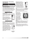
NOTE
The recommended water pressure for the model IGX
is set based on media width, model IG is set based
on air volume. A table is provided for each. Be sure
to refer to the correct table.
IGX
Housing
Media Width
(inches)
Water Pressure
(in. wg)
12 30 20
22
43¾ 36
48 42
60 61
32
66 72
96* 42
*Multiple media sections. Value represents total media width.
Model IG
CFM Range
Water Pressure
(in. wg)
800 – 3500 50
3501 – 7000 74
WARNING
Opening the manual supply valve will allow water
to pass to the media. Be sure the sump is safely
draining before opening the manual supply valve.
NOTE
The manual supply valve ships closed and must be
adjusted for proper performance.
®
Model IG / IGX Make-Up Air