


25
Start-Up - Furnaces (all units)
IMPORTANT
For the unit to function properly, all stage or
modulation valves must be set for high and low fire.
NOTE
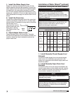
There are five furnace control options available. Be
sure to refer to the specific instructions for your
control type.
IMPORTANT
Multi furnace units may use a combination of the
available control options. Each furnace must be set-
up per the specific instructions for its control type.
IMPORTANT
Multi furnace units will use one stage or electronic
modulation controller per unit and one or two
ignition controller(s) per furnace. Each furnace will
have its own gas valve(s). Each valve must be set for
high and low fire.
NOTE
To force the unit to light for set-up purposes, the
heat switch must be closed or jumpered out. See
the Ladder Diagram on the inside of the control
center door for proper terminals to jumper out.
NOTE
If the unit is equipped with an independent
inlet air sensor (not incorporated into the stage
or modulation controller), the unit will not light
unless the outside air temperature is less than
the inlet air sensor setting. If the outside air is
greater than the inlet air sensor setting, turn the
setting to its maximum position. When set-up is
complete, reset the inlet air sensor to the proper
temperature. If the unit is equipped with a stage or
electronic modulation controller that includes an
inlet air sensor function, the inlet air sensor will be
overridden when the unit is forced to high fire.
Available Control Options
Single Furnace Units
1:1 Staged one 1-stage furnace
2:1 Staged one 2-stage furnace
8:1 Staged one 8-stage furnace
2:1 Electronic
Modulation
one 2:1 modulating furnace
4:1 Electronic
Modulation
one 4:1 modulating furnace
Two Furnace Units
1:1 Staged two independent 1-stage furnaces
2:1 Staged two independent 1-stage furnaces
4:1 Staged two independent 2-stage furnaces
16:1 Staged
one 8-stage and
one 1-stage furnace
8:1 Electronic
Modulation
one 4:1 modulating and
one 2-stage furnace
Three Furnace Units
1:1 Staged three independent 1-stage furnaces
3:1 Staged three independent 1-stage furnaces
6:1 Staged three independent 2-stage furnaces
24:1 Staged
one 8-stage and
two 1-stage furnaces
12:1 Electronic
Modulation
one 4:1 modulating,
one 2-stage and
one 1-stage furnace
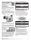
Start-Up - Single Stage Control
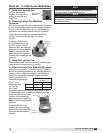
1. Send Unit to High Fire
Send the unit to high fire by
setting the temperature selector to
its maximum setting.
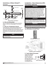
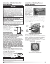
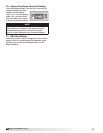
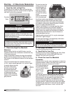
2. Check the High Fire Manifold
Pressure
Using a manometer, measure the burner manifold
pressure at the manifold pressure test port. Refer to
the Gas Train Layout in the Reference section for the
test port location.
The pressure on high fire
should be 3-1/2 in. wg for
natural gas and
10 in. wg for
LP gas.
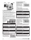
If needed, use the
high fire adjustment
screw on the staged gas
valve to adjust the high
fire manifold pressure.
Counterclockwise rotation
will decrease the gas
pressure and clockwise
rotation will increase the
gas pressure.
3. Reset the Temperature Setting
Reset the temperature setting on the temperature
selector to the desired setting.
Temperature
Selector
High Fire
Adjustment
Single Stage Manifold
Pressure (in. wg)
Natural Gas
LP
High Fire
3-1/2
10
®
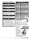
Model IG / IGX Make-Up Air