


3
Table of Contents
Installation
Clearance to Combustibles/Service Clearances ...3
Indoor Unit .................................4
Unit Arrangement DB / HZ ..................4-5
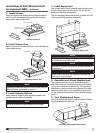
Roof Mounted Unit – Arrangement DBC .......5-6
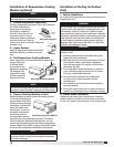
Optional Evaporative Cooling Module ...........7
Venting – Outdoor ...........................7
Indoor, All Units .....................8
Standard Indoor ....................9
Concentric, General ................10
Concentric, Horizontal ...........10-11
Concentric, Vertical ..............11-12
Two Pipe, Horizontal ................13
Two Pipe, Vertical ..................14
Electrical Wiring ........................15-16
Gas Piping ................................17
Optional Evaporative Cooler Piping .........18-19
Optional Water Wizard™ .................19-20
Optional Direct Expansion (DX) Coil Piping ...20-21
Optional Chilled Water Coil Piping .............22
Optional Building Pressure Control ............22
Start-Up
Blower ................................23-24
Furnace – All Units .........................25
Single Stage ......................25
2:1 Staged .......................26
8:1 Staged ....................26-28
2:1 Modulation ....................29
4:1 Modulation .................30-31
Optional Economizer .......................32
Optional Evaporative Cooling .................33
Optional Water Wizard™ .................34-35
Operation
Optional Water Wizard™ ....................35
Optional VAV Units .........................36
Optional Recirculating Units ..................37
Indirect Gas Fired Unit Installations
Units are listed for installation in the United States and
Canada.
•Installationofgasredductfurnacesmustconform
with local building codes. In the absence of local
codes, installation must conform to the National
Fuel Gas code, ANSI Z223.1 or in Canada, CAN/
CGA-B149 installation codes.
•Allelectricalwiringmustbeinaccordancewiththe
regulation of the National Electrical Code, ANSI/
NFPA 70.
•Unitisapprovedforinstallationdownstreamfrom
refrigeration units. In these conditions, condensate
could form in the duct furnace and provision must be
made to dispose of the condensate.
3. After storage period, purge grease before putting
fan into service.
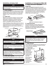
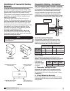
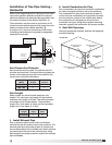
Clearance to Combustibles /
Service Clearances
Clearance to combustibles is defined as the minimum
distance required between the heater and adjacent
combustible surfaces to ensure the adjacent surface’s
temperature does not exceed 90 degrees above the ambient
temperature.
*Reference venting guidelines for combustion blower clearances.
Floor Top Sides Ends
Indirect Fired
Units*
0 inches
(0 mm)
0 inches
(0 mm)
0 inches
(0 mm)
0 inches
(0 mm)
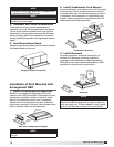
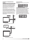
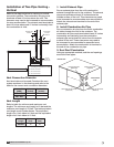
Clearances for component removal (such as evaporative
cooler media) should be 6 in. wider than the width of the
module itself.
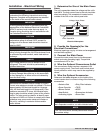
Recommended Minimum Service Clearances
Housing 32
and less
42 inches
(1067 mm)
on the
controls side of the unit
Sequence of Operation, Furnace –
2:1 Staged ............................38
2:1 Modulation ......................39-40
Operation of Controller –
4:1 Modulation/8:1 Staged Controller ....40-41
Sequence of Operation, Furnace –
4:1 Modulation ......................41-42
8:1 Staged .........................43-44
Ignition Controller ..........................44
Economizer ...............................45
Troubleshooting
Blower ...................................46
Motor Over Amps ..........................47
Insufficient / Too Much Airflow ................48
Excessive Noise / Vibration ..................49
Furnace – Staged ..........................50
2:1 Modulation ....................51
4:1 Modulation .................52-53
8:1 Staged ....................54-55
Optional Evaporative Cooling .................56
Optional Water Wizard™ ....................57
Maintenance
Routine ...............................58-59
Fall ...................................60-61
Reference
Vent Connections ..........................62
Model IG – Single or 2 Stage .................63
8:1 Staged ......................64
2:1 Modulation ...................65
4:1 Modulation ...................66
Model IGX – Blower Control Center ............67
Single or 2 Stage .................68
8:1 Staged ......................68
2:1 Modulation ...................69
4:1 Modulation ...................69
Performance Table .........................70
Start-Up Checklist ..........................71
Maintenance Log ...................Backcover
Warranty ..........................Backcover
®
Model IG / IGX Make-Up Air