


38
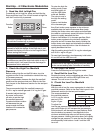
Sequence of Operation
2:1 Staged Sequence
1. Exhaust Fan Contact (S1) Manually Closed
(optional)
• PowerpassesthroughN.C.contactonexhaustfan
overload (ST2 OL), which is closed if exhaust fan
(M2) has not overloaded
• Powerpassestoexhaustfanstarter(ST2)
• N.O.contactonexhaustfanstarter(ST2)is
energized and closed
• Powerpassestoandenergizesexhaustfan(M2)
2. Supply Fan Contact (S2) Manually Closed
• PowerpassesthroughN.C.eld-suppliedre
contact (FSC)
• PowerpassesthroughoptionalN.O.contacton
exhaust fan starter (ST2), which is closed when the
optional exhaust starter (ST2) is activated
• PowerpassesthroughN.C.contactonsupply
starter overload (ST1 OL), which is closed if the
supply fan has not overloaded
• PowerpassesthroughN.C.contactonoptional
freeze protection timer (RT4), which is closed if the
temperature has remained above the set point
• Powerpassestoandenergizesoptionalinlet
damper (D1), which opens
• Powerpassesthroughoptionaldamperlimitswitch
(DL1), which is energized and closed if the optional
inlet damper is open. It may take several minutes
for the damper to fully open and for the damper
limit switch to close
• Powerpassestoandenergizesfanrelay(RF)
• PowerpassesthroughN.O.contactonfanrelay
(RF), which is closed once the fan relay (RF) is
activated
• Powerpassestoandenergizesstarterrelay(ST1)
• N.O.contactonsupplyfanstarter(ST1)is
energized and closed
• Supplyfan(M1)starts
3. Heat Contact (S4) Manually Closed
• PowerpassesthroughN.O.fanrelay(RF),whichis
energized and closed if the supply fan (M1) is on
• PowerpassesthroughN.C.contactonoptional
inlet air sensor (TS4), which is closed if inlet air
temperature is below the set point
• Powerpassestoandenergizestheheatrelay(RH)
• N.O.contactonheatrelay(RH)closes
• 24VACissuppliedtostagecontroller(SC1)
• Ifthedischargetemperatureislessthantheset
point on the discharge air sensor (TS2) and the
high temperature limit control (HLC1) has not
been tripped, the N.O. contact for furnace stage
controller will close
• Powerwillbesuppliedtotheignitioncontroller
(IC1), which will begin its sequence of operation
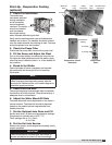
4. Ignition Controller (IC1) Sequence of Operation
• TheN.O.contactonairprovingswitch(PS2)isopen
• Theignitioncontroller(IC1)energizesthe
combustion blower relay (CR)
• N.O.contactoncombustionblowerrelay(CR)
closes
• Powerpassestoandenergizesthecombustion
blower (CM)
• TheN.O.contactonairprovingswitch(PS2)closes
• Theignitioncontroller(IC1)beginsa15second
pre-purge
• Thehighrerelay(RT3)isenergizedandtheN.O.
contact on high fire relay (RT3) closes
• Themaingasvalve(MV)fullyopens(100%)
• Igniterbeginssparking
• 10secondtrialforignitionbegins
• Thefurnacewilllightathighre(100%)
• Whentheameisdetected,theigniterstops
sparking
• Thefurnacewillremainathighre(100%)forat
least 10 seconds
• Highrecontact(RT3)willopen
• Furnacestagestomaintainthedischargeair
temperature set point (SC1)
5. High Fire – Low Fire Sequence of Operation
• Thefurnacelightsathighre(100%)andremains
at high fire for 10 seconds
• Ifthedischargetemperatureisabovethedischarge
air sensor (TS2) set point, the N.O. furnace stage 2
controller contact (SC2), will open and the furnace
will go to low fire (50%)
• Ifthefurnaceisatlowre(50%)andthedischarge
temperature is above the discharge air sensor
(TS2) set point, the furnace stage 1 contact (SC1)
will open and the furnace will shut down
• Ifthefurnaceisatlowre(50%)andthedischarge
temperature is below the discharge air sensor (TS2)
set point, the furnace stage 2 contact (SC2) will
close and the furnace will go to high fire
6. Optional Evaporative Cooling Contact (S4)
Closed*
• N.O.contactonfanrelay(RF)isenergizedand
closed
• PowerpassesthroughN.O.contactonoptional
inlet air sensor (TS4), which is energized and
closed if the inlet air temperature is above the set
point
• Powerpassestoandenergizescoolrelay(RC)
• N.O.contactoncoolrelay(RC)isenergizedand
closed
• Powerpassestoevaporativecoolingpump(P1)
*If DX or chilled water coils are used rather than an
evaporative cooler, the cooling sequence of operation
will depend on the coil controls. Cooling coil controls are
supplied by others.
®
Model IG / IGX Make-Up Air