


19
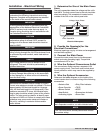
NOTE
The following instructions are provided for
evaporative coolers equipped with the Water
Wizard™ only. Additional instructions are provided
for evaporative coolers equipped with the auto drain
and fill or bleed-off.
WARNING
Disconnect and lock-out all power and gas before
performing any maintenance or service to the unit.
Failure to do so could result in serious injury or
death and damage to equipment.
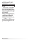
NOTE
Solenoid(s) may be provided by manufacturer (if
ordered) or by others.
CAUTION
Any wiring deviations may result in personal injury or
property damage. Manufacturer is not responsible
for any damage to or failure of the unit caused by
incorrect final wiring.
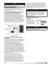
6 in. min.
6 in. min.
Drain
Trap
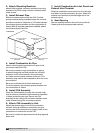
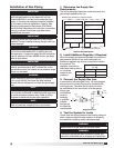
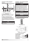
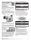
1. Install the Water Supply Line
Supply line opening requirements vary by unit size
and arrangement and are field-supplied. Connect the
water supply line to the float valve through the supply
line opening in the evaporative cooling unit. Install
the 1/2inch normally closed solenoid (Valve A) in the
supply line. Install the 1/4 inch normally open solenoid
(Valve B) between the supply line and the drain line as
shown.
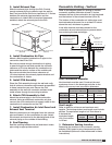
2. Install the Drain Line
Connect an unobstructed drain line to the sump drain
overflow connection. Install the 3/4 in. normally open
solenoid (Valve C) between the sump drain connection
and the drain line. A
trap should be used to
prevent sewer gas from
being drawn into the
unit. Refer to Drain Trap
drawing.
3. Check/Adjust Water Level
Check the water level in the sump tank. The water
level should be above the pump intake and below the
overflow. Adjust the float as needed to achieve the
proper water level.
Evaporative Cooling with the Water Wizard™
Installation of Water Wizard
TM
(optional)
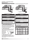
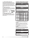
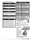
Water Wizard™ Valves
(when provided by manufacturer)
Unit
Model
Assembly
Number
Mfg.
Part
Number
ASCO™
Part
Number
Solenoid
Type
De-
Energized
Position
Diameter Qty.
IGX -
H12/H22
IGX - H32
(<9000 cfm)
852370
461262 8210G2
Supply Closed
1/2 inch
(12.7 mm)
1
383086 8210G34
Supply
Line
Drain
Open
1/2 inch
(12.7 mm)
1
IGX - H32
(≥9000 cfm)
852371
383088 8210G9
Supply Closed
3/4 inch
(19.05 mm)
1
383086 8210G34
Supply
Line
Drain
Open
1/2 inch
(12.7 mm)
1
Part numbers subject to change.
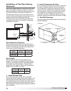
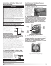
1. Install Normally Closed Supply Line/
Solenoid
Connect the water supply line to the manual supply
valve in the unit. Install the supply solenoid in the
supply line, upstream of the manual supply valve and
below the roofline.
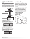
2. Install Normally Open Drain Line/
Solenoid
Connect the drain line to the supply line between the
manual supply valve and the supply solenoid. Install a
drain solenoid in the drain line, below the roof line. A
trap should be installed in the drain line.
®
Model IG / IGX Make-Up Air