


18
Installation - Evaporative Cooler
Piping (optional)
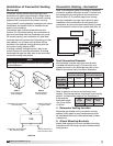
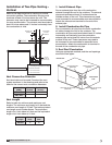
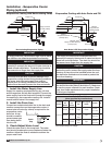
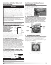
Evaporative Cooling with Auto Drain and Fill
Auto Drain & Fill Evaporative Piping
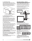
1. Install the Water Supply Line
Supply line opening requirements vary by unit size
and arrangement and are field-supplied. Connect the
water supply line to the float valve through the supply
line opening in the evaporative cooling unit. Install a
manual shutoff valve in the supply line.
2. Install the Drain Line
Connect an unobstructed drain line to the drain and
overflow connections on the evaporative cooler. A
manual shut off valve (by others) is required for the
evaporative cooler
drain line. A trap
should be used to
prevent sewer gas
from being drawn
into the unit.
3. Check/Adjust Water Level
Check the water level in the sump tank. The water
level should be above the pump intake and below the
overflow. Adjust the float as needed to achieve the
proper water level.
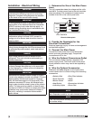
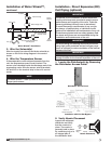
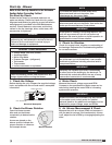
Evaporative Cooling with Recirculating Pump
Supply Line
Overflow
Trap
Drain Line
Supply Line Valve
(normally closed)
Drain Line Valve
(normally open)
Recirculating Evaporative Piping
IMPORTANT
All supply solenoids, valves and all traps must be below
the roofline or be otherwise protected from freezing.
IMPORTANT
The supply line should be of adequate size and
pressure to resupply the amount of water lost due to
bleed-off and evaporation. The drain line should be
the same size or larger than the supply line.
CAUTION
Provisions must be taken to prevent damage to the
evaporative cooling section during freezing conditions.
The sump, drain lines and supply lines must be
drained prior to freezing conditions or an alternate
method must be used to protect the lines and media.
6 in. min.
6 in. min.
Drain
Trap
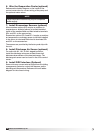
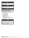
IMPORTANT
The supply line should be of adequate size and
pressure to resupply the amount of water lost due to
bleed-off and evaporation. The drain line should be
the same size or larger than the supply line.
CAUTION
All solenoid valves and traps must be installed
below the roof to protect the supply water line from
freezing. If they cannot be installed below the roof,
an alternative method must be used to protect the
lines from freezing.
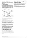
IMPORTANT
The supply solenoid (Valve A) is NOT the same as
the drain solenoids (Valve B and Valve C). Make sure
to use the proper solenoid for each location. Check
your local code requirements for proper installation
of this type of system.
Sump Overflow
Trap
Drain Line
Sump Drain
Supply Line
VALVE A
Supply Solenoid
(normally closed)
VALVE C
Sump Drain Solenoid
(normally open)
VALVE B
Supply Line Drain Solenoid
(normally open)
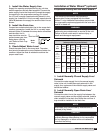
Auto Drain & Flush Valves
(when provided by manufacturer)
Assembly
Number
Mfg.
Part
Number
ASCO™
Part
Number
Solenoid
Type
De-Energized
Position
Diameter
Qty.
852178
461262 8210G2
Supply Closed
1/2 inch
(12.7 mm)
1
461263 8262G262
Supply
Line
Drain
Open
1/4 inch
(6.35 mm)
1
461264 8210G35
Sump
Drain
Open
3/4 inch
(19.05 mm)
1
Part numbers subject to change.
®
Model IG / IGX Make-Up Air