


22
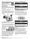
1. Verify Coil Hand Designation
Check the coil hand
designation to ensure that
it matches the system.
Coils are generally
plumbed with the supply
connection located on
the bottom of the leaving
air-side of the coil and the
return connection at the top of the entering air-side
of the coil. This arrangement provides a counter flow
heat exchanger and positive coil drainage.
2. Check the Coil for Leaks
Pressurize the coil to 100 psig with dry nitrogen or
other suitable gas. The coil should be left pressurized
for a minimum of 10 minutes. If the coil holds the
pressure, the hook-up can be considered leak free.
If the pressure drops by 5 psig or less, re-pressurize
the coil and wait another 10 minutes. If the pressure
drops again, there is likely one or more small leaks
which should be located and repaired. Pressure losses
greater than 5 psig indicate a large leak that should be
isolated and repaired.
3. Connect the Supply & Return Lines
Connect the supply and return lines as shown above.
4. Install the Drain Line
Connect an unobstructed
drain line to the drain pan.
A trap should be installed
to prevent sewer gas from
being drawn into the unit.
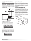
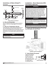
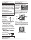
Installation of Chilled Water Coil
Piping (optional)
6 in. min.
6 in. min.
Drain
Trap
Hot Return
Connection
Cold Supply
Connection
Entering
Air
Leaving
Air
IMPORTANT
Guidelines for the installation of the cooling coil
have been provided to ensure proper performance
of the coils and their longevity. These are general
guidelines that may have to be tailored to meet the
specific requirements of any one job. As always,
a qualified party or individual should perform the
installation and maintenance of the coil. Protective
equipment such as safety glasses, steel toe boots
and gloves are recommended during the installation
and maintenance of the coil.
When installing couplings, do not apply undue
stress to the connection. Use a backup pipe
wrench to avoid breaking the weld between the coil
connection and the header.
All field-piping must be self-supporting. System
piping should be flexible enough to allow for the
thermal expansion and contraction of the coil.
IMPORTANT
All traps must be installed below the roof line or be
otherwise protected from freezing.
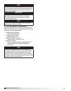
Installation of Building Pressure
Control (optional)
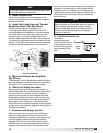
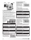
1. Mount Pressure Tap
Using the factory provided bracket, mount the
pressure tap to the
outside of the unit.
Choose a location
out of the prevailing
winds and away from
supply or exhaust
fans to assure
accurate readings.
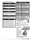
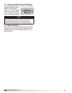
2. Run Pressure Tap Lines
Run a pressure tap line from the pressure tap on the
outside of the unit to the low pressure tap on the back
of the photohelic gauge. Run a second pressure tap
line from the high pressure tap on the back of the
photohelic gauge to the space. Fifty feet of tubing is
supplied with the unit.
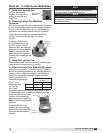
3. Set the Building Pressure
The pressure gauge is used to set the desired building
pressure. The pressure is set by adjusting the knobs
for the upper and lower pressure limits. Typical
settings are 0.0 in. wg for the lower and 0.10 in. wg for
the upper pressure setting.
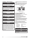
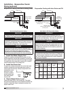
Connections for Photohelic Gauge
Factory
Wiring
High
Pressure
Tap to
space
Low
Pressure
Tap to
outside
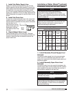
Typical Photohelic Gauge Settings
Pressure Setting Knobs
Pressure Setting
Needles
Pressure Indicating
Needle
®
Model IG / IGX Make-Up Air