


17
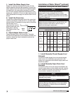
Installation of Gas Piping
IMPORTANT
All gas piping must be installed in accordance
with the latest edition of the National Fuel Gas
Code ANSI/Z223.1 and any local codes that may
apply. In Canada, the equipment shall be installed
in accordance with the Installation Code for Gas
Burning Appliances and Equipment (CGA B149)
and Provincial Regulations for the class. Authorities
having jurisdiction should be consulted before
installations are made.
IMPORTANT
All piping should be clean and free of any foreign
material. Foreign material entering the gas train can
cause damage.
WARNING
All components of this or any other gas fired heating
unit must be leak tested prior to placing the unit
into operation. A soap and water solution should be
used to perform this test. NEVER test for gas leaks
with an open flame.
IMPORTANT
Do NOT connect the unit to gas types other than
what is specified and do NOT connect the unit to
gas pressures that are outside of the pressure range
shown on the label.
WARNING
When leak testing pressures equal to or less than
14in. wg (3.5 kPa), first close the field-installed
shutoff valve to isolate the unit from the gas supply
line.
NOTE
When connecting the gas supply, the length of the
run must be considered in determining the pipe size
to avoid excessive pressure drop. Refer to a Gas
Engineer’s Handbook for gas pipe capacities.
NOTE
Each furnace has a single 3/4-inch connection.
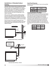
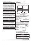
1. Determine the Supply Gas
Requirements
The unit’s nameplate states the requirements for the
gas being supplied to the unit.
4. Test the System for Leaks
Check both the supply lines and the factory piping for
leaks. Apply a soap and water solution to all piping
and watch for bubbling which indicates a leak.
WARNING
NEVER test for a gas leak with an open flame.
WARNING
The factory piping has been checked for leaks, but
should be rechecked due to shipping and installation.
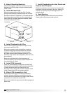
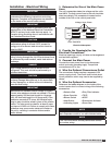
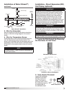
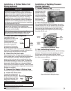
Indirect Gas Nameplate
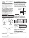
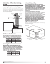
2. Install Additional Regulator if Required
When the supply gas pressure exceeds the maximum
gas pressure shown on the unit’s nameplate, an
additional regulator (by others) is required to reduce
the pressure. The
regulator must have a
listed leak limiting device
or it must be
vented to the
outdoors.
Supply Gas Pressure Range
(in. wg)
Minimum Maximum
Natural 6 14
LP 10 14
“W.C.
“W.C.
“W.C.
F
PSI
“W.C.
MAX BTU/HR
BTU/H MAX
NORMAL MANIFOLD
PRESSURE
PRESSION DÕADMISSION
NORMALE
MIN GAS
PRESSURE
PRESSION DE GAZ
TYPE OF GAS
NATURE DU GAZ
MIN BTU/HR
BTU/H MIN
MIN GAS PRESSURE
FOR MAX OUTPUT
PRESSION DE GAZ MIN
POUR PUISSANCE MAX
MAX GAS
PRESSURE
PRESSION DE GAZ
MAX
DESIGN DT
DT NORMALE
EQUIPPED FOR
CONCU POUR
SCFM
“W.C.
EXTERNAL STATIC PRESSURE
PRESSION STATIQUE EXTERIEURE
AGAINST
CONTE
Minimum gas pressure for maximum output
Maximum gas pressureType of gas
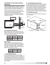
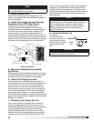
To
Controls
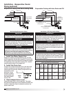
Gas Cock
From
Gas
Supply
6 in. Trap
1/8 in. Plugged Tap
Ground Joint Union
Supply Gas Line
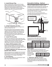
3. Connect the Supply Gas Line
A manual shut off valve (gas cock), 1/8 inch plugged
test port and 6 inch drip leg must be installed prior
to the gas train. The valve and the test port must
be accessible for the connection of a test gauge.
Supply gas
connections
must be
made by
a qualified
installer
and are not
furnished by
manufacturer.
®
Model IG / IGX Make-Up Air