


11
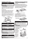
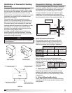
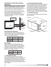
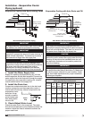
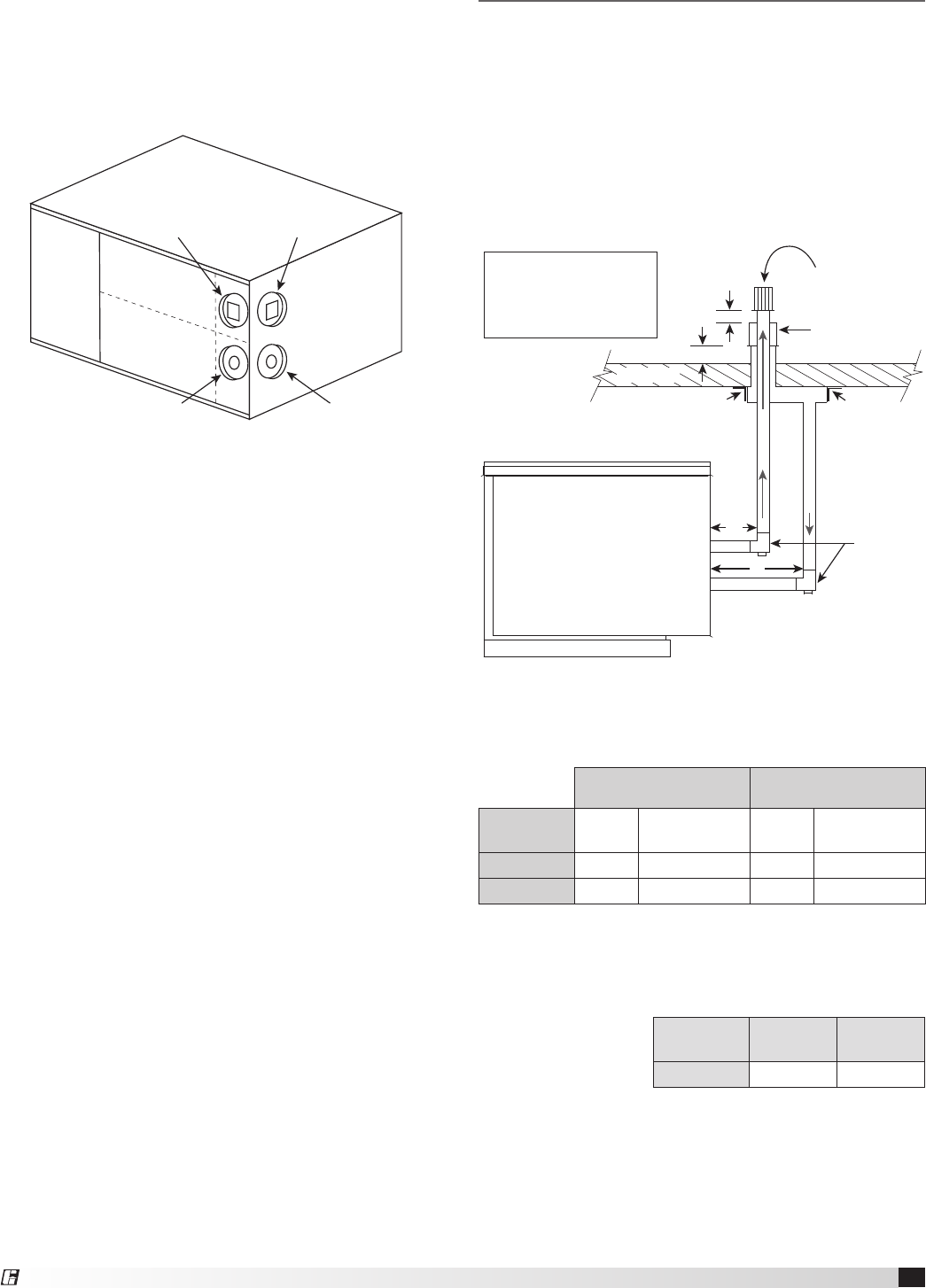
Concentric Venting – Vertical
Refer to the diagram below for venting on vertical
concentric systems. Maintain at least 12 inches
between the top of the combustion air inlet terminals
and the bottom of the exhaust terminal. (Dim. B).
The bottom of the combustion air intake pipe must
terminate above the snow line or at least 12 inches
above the roof, whichever is greater.
A tee with cleanout must be provided on the
combustion air and exhaust pipe to prevent debris
from entering the heat exchanger.
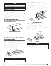
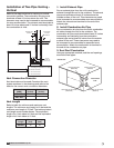
4. Install Combustion Air Pipe
Attach a field-supplied combustion air pipe to the
concentric side of the CVA.
Be sure to provide enough combustion air piping
to pass through the wall and provide the minimum
clearance of 2 inches between the combustion air
intake and the exterior surface of the outside wall.
Be sure to maintain the minimum clearance of
12inches between the exhaust pipe termination and
the combustion air intake.
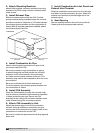
5. Install CVA Assembly
Place the CVA assembly through the wall and verify
that all minimum clearance requirements as specified
in these instructions are met. Secure the CVA
assembly to the wall with corrosion resistant sheet
metal screws through the mounting brackets.
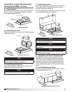
6. Attach CVA Assembly to Unit
Attach the exhaust pipe to the unit’s combustion
exhaust. Using an additional combustion air pipe,
connect the unit’s combustion air supply intake to the
combustion air connection on the CVA.
7. Install Combustion Air Inlet Guard and
Exhaust Vent Terminal
Slide the combustion air inlet guard over the exhaust
pipe and fasten it to the combustion air pipe. Attach
the exhaust vent terminal to the discharge end of the
exhaust piping on the outside of the building.
8. Seal Opening
Seal the opening between the wall and the air intake
pipe using an appropriate method.
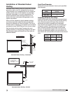
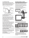
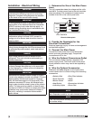
Vent Length
Refer to table for minimum and maximum vent
lengths. The total equivalent vent length must include
elbows. The equivalent length of a 4 inch elbow is
6feet and the
equivalent length
of a 6inch elbow
is 10feet.
Vent
Length
Minimum
(feet)
Maximum
(feet)
Vertical
10 70
3. Install Exhaust Pipe
Slide the exhaust pipe through the CVA. Provide
enough exhaust piping to pass through the wall (or
floor) and provide the minimum clearance of 12inches
between the exhaust pipe termination and the
combustion air intake. With all required clearances
satisfied, attach the exhaust pipe to the CVA.
1. Determine Venting Location
Determine the location of the concentric venting
adapter (CVA) based on any clearances that must
be maintained (follow all codes referenced in these
instructions).
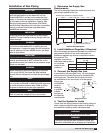
Vent Connection Diameter
Vent terminals must be used. Construct the vent
system as shown in the drawings and refer to the
table for the correct vent connection diameters.
Non-Concentric Vent
Connection Diameter
Concentric Vent
Connection Diameter
Furnace
Size (MBH)
Exhaust
(inches)
Combustion Air
(inches)
Exhaust
(inches)
Combustion Air
(inches)
75-175
4 4 4 6
200-400
6 6 6 8
A = 12 inch minimum, but
should size according to
expected snow depth
B = 12 inch minimum
C = 12 inch minimum
Roof Line
Exhaust Vent
Terminal
EXHAUST
COMBUSTION AIR
Combustion Air
Inlet Terminal
Mounting
Bracket
Tee with
drip leg and
clean-out cap
Mounting
Bracket
C
C
B
A
Exhaust Connection
(Model IGX)
Exhaust Connection
(Model IG)
Combustion Air Connection
(Model IG)
Combustion Air Connection
(Model IGX)
DISCHARGE
END
INTAKE END
®
Model IG / IGX Make-Up Air