


26
Start-Up - 2:1 Staged Control
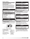
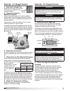
1. Send Unit to High Fire
Send the unit to high fire by setting
the temperature selector to its
maximum setting.
2. Check the High Fire
Manifold Pressure
Using a manometer, measure the burner manifold
pressure at the manifold pressure test port. Refer to
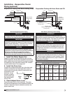
the Gas Train Layout in the Reference section for the
test port location.
The pressure on high fire should be 3-1/2 in. wg for
natural gas and 10 in. wg for LP gas.
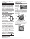
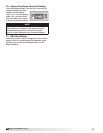
If needed, use the high fire adjustment screw on the
combination gas valve to adjust the high fire manifold
pressure. Counterclockwise rotation will decrease the
gas pressure and clockwise rotation will increase the
gas pressure.
3. Send Unit to Low Fire
Remove and isolate the wire from the high fire terminal
on the combination gas valve to send the unit to low
fire.
4. Check the Low Fire Manifold Pressure
Using a manometer, measure the burner manifold
pressure at the manifold pressure test port. Refer to
the Gas Train Layout in the Reference section for the
test port location.
The pressure on low fire
should be 7/8 in. wg
for natural gas and
2-1/2 in. wg for LP
gas.
If needed use the low fire adjustment screw on the
combination gas valve to adjust the low fire manifold
pressure. Counterclockwise rotation will decrease the
gas pressure and clockwise rotation will increase the
gas pressure. Once the low fire manifold pressure is
set, reattach the high fire wire to the high fire terminal.
5. Reset the Temperature Setting
Reset the temperature setting on the temperature
selector to the desired setting.
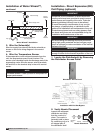
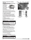
High Fire
Adjustment
Low Fire
Adjustment
High Fire
Terminal
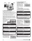
Start-Up - 8:1 Staged Control
IMPORTANT
8:1 staged furnaces use two manifolds and two
staged gas valves per furnace. The high and low fire
manifold pressure must be checked and properly
set on each manifold.
IMPORTANT
Confirm that the discharge air sensor is installed in
the duct, at least three duct diameters downstream
of the furnace.
WARNING
Once the unit is forced to high fire, it will remain at
high fire until the Function key is pressed.
NOTE
Forcing the unit to high fire during warm or hot
weather conditions may cause the high limit switch
to trip. If the switch trips, it will reset once the
discharge air temperature has reached a safe level.
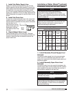
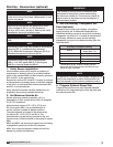
Two Stage Manifold
Pressure (in. wg)
Natural Gas
LP
Low Fire
7/8
2-1/2
High Fire
3-1/2
10
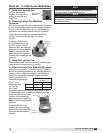
Temperature
Selector
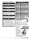
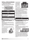
1. Send the Unit to High Fire
For the furnace to light, the heat switch must be
closed or jumpered out. Reference the unit ladder
diagram for proper terminals to jumper.
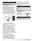
To send the unit to high fire, press and hold the Up,
Down and Enter keys. The middle LED light, L2, will
flash on the screen when the unit is forced to high fire.
The unit will remain at high fire until the Function key
is pressed (middle LED light, L2, will stop flashing).
2. Check the High Fire Manifold
Pressure
Using a manometer, measure the high fire burner
manifold pressure for each furnace at the pressure
test port. Refer to the Gas Train Layout in the
Reference section for the test port location.
The recommended high fire manifold pressure is
3-1/2in. wg for natural gas and 10 in. wg for LP gas.
If needed, adjust the high fire screws on each staged
gas valve to set both high fire manifold pressures.
Counterclockwise rotation will decrease the gas
pressure and clockwise rotation will increase the gas
pressure.
Function
L1 L2 L3
Enter
Up
Down
®
Model IG / IGX Make-Up Air