


29
Start-Up - 2:1 Electronic Modulation
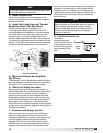
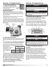
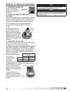
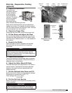
1. Send Unit to High Fire
Turn the temperature
selector to its maximum
setting to send the unit
to high fire.
2. Check the High Fire Manifold
Pressure
With the unit at high fire, use a manometer to measure
the burner manifold pressure at the manifold pressure
test port. See the Gas Train Layout in the Reference
section for the manifold pressure test port location.
The recommended high fire manifold pressure is
3-1/2in. wg for natural gas and 10in. wg for
LP gas.
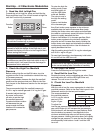
If needed, use the high
fire adjustment screw on
the shut-off gas valve to
adjust the high fire manifold
pressure. Counterclockwise
rotation will decrease the
gas pressure and clockwise
rotation will increase the gas
pressure.
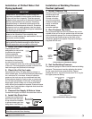
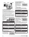
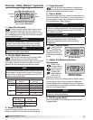
3. Send Unit to Low Fire
Remove and isolate one wire from the modulating gas
valve terminal to send the unit to low fire.
4. Check the Low Fire Manifold Pressure
With the unit at low fire, use a manometer to measure
the burner manifold pressure at the manifold pressure
test port. See the Gas Train Layout in the Reference
section for the manifold pressure test port location.
The recommended low
fire manifold pressure is
7/8in. wg for
natural gas and
2-1/2in. wg
for LP gas.
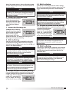
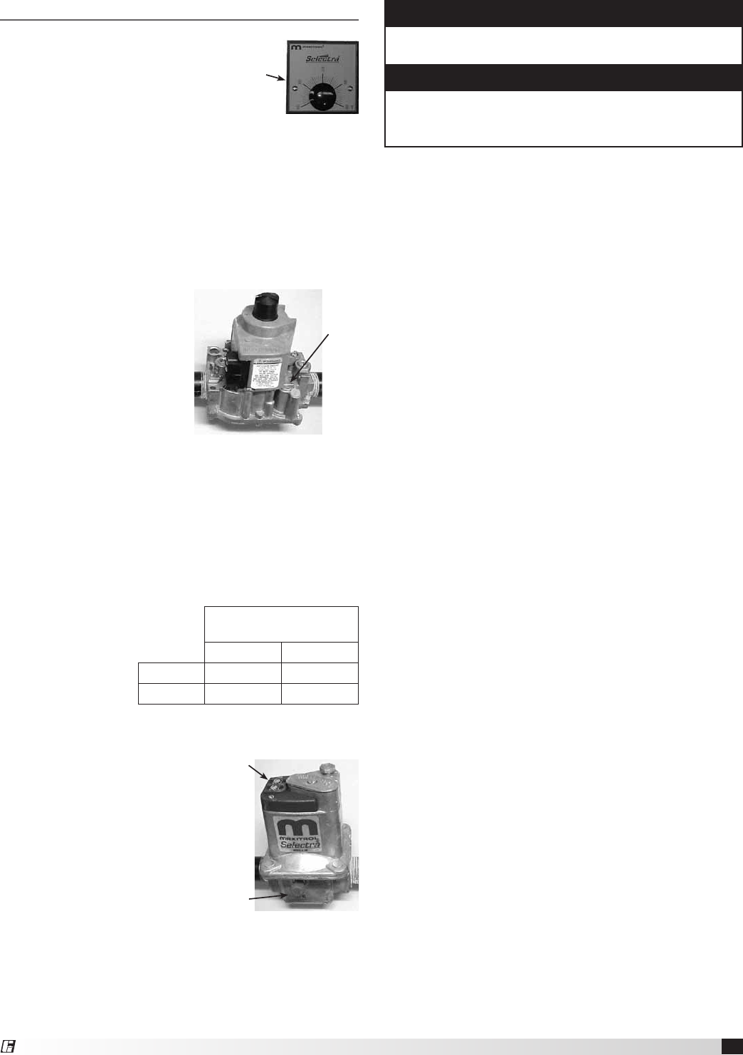
If needed, use the low fire adjustment screw on the
modulating gas valve to adjust the low fire manifold
pressure. Counterclockwise
rotation will decrease the
gas pressure and clockwise
rotation will increase the gas
pressure.
Once the low fire is set,
reattach the disconnected
wire to the modulating valve
and reset the temperature
selector.
Low Fire
Adjustment
Terminal
NOTE
The low fire manifold pressure should always be
rechecked after adjusting the high fire.
NOTE
Once the high and low fire manifold pressures are
properly set, reset the discharge air temperature to
the desired setting.
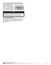
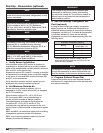
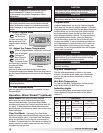
2:1 Manifold Pressure
(in. wg)
Natural Gas LP
Low Fire
7/8 2-1/2
High Fire
3-1/2 10
High Fire
Adjustment
Temperature
Selector
®
Model IG / IGX Make-Up Air