


MODEL SOLU COMP II SECTION 8.0
TROUBLESHOOTING
8.2.2 pH Sensitive Glass Membrane is Broken
The Solu Comp II continuously measures the impedance between the sensor solution ground and the inside of the
pH-sensing electrode. If the glass membrane is intact, the impedance is normally between 10 MΩ and 1000 MΩ.
If the membrane is cracked or broken, the impedance drops below 10 MΩ. If the membrane is cracked or broken,
the sensor must be replaced.
8.2.4 RTD for Sensor 1 or Sensor 2 Open or Shorted.
There is an open or short in the sensor RTD or wiring.
A. If sensor is being installed for the first time, check the wiring connections. See Section 3.2.
B. Disconnect the sensor from the analyzer and measure the resistance between the RTD lead wires. See the
sensor manual to identify the RTD leads. If there is an open or short circuit, replace the sensor.
C. If there is no open or short, check the analyzer. See Section 8.8.
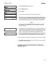
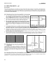
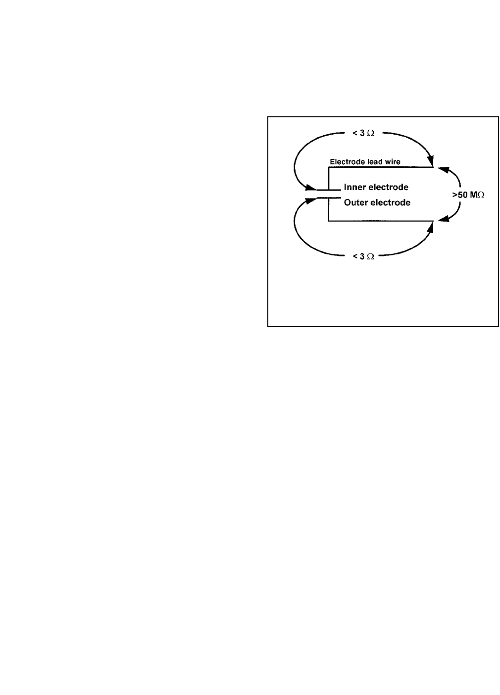
FIGURE 8-1. Continuity and Leakage Check.
Use an ohmmeter to measure the resistances indi-
cated. Be sure the sensor is dry when checking
the resistance.
8.2.3 Conductivity Sensor Open or Shorted
Open or shorted means an open or short circuit in the
conductivity sensor or wiring. An open error may also
mean that the sensor is not immersed in the process liq-
uid.
A. If sensor is being installed for the first time, check the
wiring connections. See Section 3.2.
B. Verify that the sensor is completely immersed in the
process liquid.
C. Remove the sensor from the process liquid. Rinse
with water. Inspect the sensor for obvious signs of
damage such as cracks or chips. Verify that the vent
holes are not blocked.
D. Disconnect the sensor from the analyzer and
check continuity and leakage resistance as shown
in Figure 8-1. If the resistances are not in limits,
replace the sensor.
E. If the resistances are in limits, check the analyzer.
See Section 8.7.
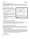
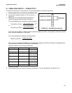
8.2.5 RTD Sense Line for Sensor 1 or Sensor 2 is Open.
The Solu Comp II measures temperature using a three-wire RTD. See Figure 8-5. The in and return leads connect
the RTD to the measuring circuit in the analyzer. A third wire, called the sense line, is connected to the return line.
The sense line allows the analyzer to correct for the resistance of the in and return leads and to correct for changes
in lead wire resistance with temperature.
A. Verify that all wiring connections are secure.
B. The analyzer can be operated with the sense line open. The measurement will be less accurate because the
analyzer can no longer correct for lead wire resistance and for changes in lead wire resistance with ambient
temperature. However, if the sensor is to be used at approximately constant temperature, the lead wire resist-
ance error can be eliminated by calibrating the sensor at the measurement temperature. Errors caused by
changes in lead wire resistance with changes in ambient temperature cannot be eliminated.To make the error
message disappear, connect the RTD sense and return terminals with a jumper.
8.2.6 EEPROM Failure.
Call the factory at (800) 854-8257.
66