


34
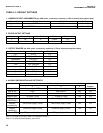
Alarm relays are single pole-double throw (SPDT). When an alarm is activated, the coil is energized.
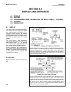
When an alarm activates, AL1, AL2, or AL3 (as appropriate) appears periodically in the display.
4. USP 24 ALARM. Any alarm, if assigned to sensor 2 (conductivity) can be configured as a USP 24 alarm. A
USP 24 alarm activates when the non-temperature-corrected conductivity (raw conductivity) of the water is
within a user-selectable percentage (safety range) of the USP 24 limit. For example, at 40°C the USP 24 limit
is 1.7 µS/cm. If the safety range is 10%, the USP 24 alarm activates when the raw conductivity exceeds 1.7 -
(0.1 x 1.7) or 1.53 µS/cm.
MODEL SOLU COMP II SECTION 5.0
PROGRAMMING THE ANALYZER
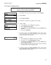
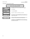
5.4 CONFIGURING ALARMS AND ASSIGNING SETPOINTS
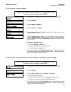
5.4.1 Purpose
This section describes how to do the following:
1. assign an alarm relay to a sensor,
2. set the alarm logic to high or low,
3. assign values to the alarm setpoints,
4. set the alarm deadbands.
ALARM RELAYS MUST BE CONFIGURED BEFORE ASSIGNING SETPOINTS.
5.4.2 Definitions
1. ASSIGNING ALARMS. There are three alarms (AL1, AL2, and AL3). Alarms 1 and 2 can be assigned to any
sensor. For example, AL1 and AL2 can be assigned to sensor 1 with, perhaps, one alarm configured as a high
alarm and the other as a low alarm, and AL3 can be assigned to sensor 2. Alarm 3 can be assigned to either
sensor or used as a fault alarm. The fault alarm activates when a fault exists in a sensor or the analyzer.
2. FAULT ALARM. A fault condition exists when the Solu Comp II detects a problem with a sensor or with the ana-
lyzer that is likely to cause seriously erroneous readings. If Alarm 3 was programmed as a fault alarm, the
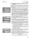
alarm 3 relay will activate. The word Fault will appear alternately in the display with the reading.
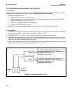
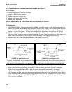
3. ALARM LOGIC, SETPOINTS, AND DEADBANDS. See Figures 5-2 and 5-3.
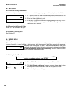
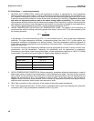
FIGURE 5-2. High Alarm Logic
The alarm activates when the pH exceeds the high
setpoint. The alarm remains activated until the reading
drops below the value determined by the deadband.
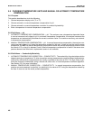
FIGURE 5-3. Low Alarm Logic
The alarm activates when the conductivity drops below the
low setpoint. The alarm remains activated until the reading
increases above the value determined by the deadband.