


3.2 POWER, ALARM, OUTPUT, AND SENSOR CONNECTIONS
The Solu Comp II is available in two mounting configurations.The positions of the power, alarm, output, and sen-
sor terminal blocks are different in each. Refer to the table to find the correct drawing.
For best EMI/RFI protection use
shielded output signal cable
enclosed in an earth-grounded
metal conduit. Connect the
shield to earth ground at termi-
nal 4 on TB1.
AC wiring should be 14 gauge or greater. Provide a switch or breaker to disconnect the analyzer from the main power
supply. Install the switch or breaker near the analyzer and label it as the disconnecting device for the analyzer.
Keep sensor and output signal wiring separate from power wiring. Do not run sensor and power wiring in the same
conduit or close together in a cable tray.
NOTE
For sensors without solution ground, please use the RC kit included with the instrument.
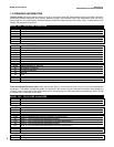
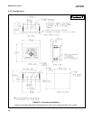
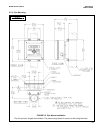
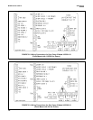
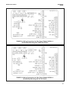
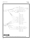
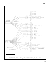
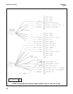
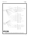
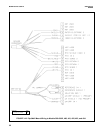
MODEL MOUNTING POWER FIGURE
1055pH-01-10 Panel 115/230 Vac 3-2
1055pH-02-10 24 Vdc 3-3
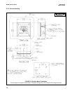
1055pH-01-11 Surface/Pipe 115/230 Vac 3-4
1055pH-02-11 24 Vdc 3-5
WARNING: RISK OF ELECTRICAL SHOCK
AC connections and grounding must be in compliance
with UL 508 or local electrical code. DO NOT apply
power to the analyzer until all electrical connections are
verified and secure.
SECTION 3.0.
WIRING
3.1 PREPARING CONDUIT OPENINGS
3.2 POWER, ALARM, OUTPUT, AND SENSOR
CONNECTIONS
MODEL SOLU COMP II SECTION 3.0
WIRING
3.1 PREPARING CONDUIT OPENINGS
The number of conduit openings and the location depend on
the model.
Conduit openings accept 1/2-inch conduit fittings or PG 13.5
cable glands. To keep the case watertight, block unused
openings with NEMA 4X or IP65 conduit plugs.
NOTE
Use watertight fittings and hubs that comply with the
requirements of UL514B. Connect the conduit hub to the
conduit before attaching the fitting to the analyzer (UL508-
26.16).
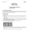
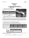
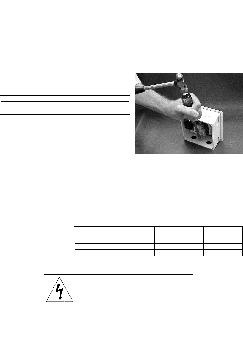
Figure 3-1 shows how to remove the knockouts. The knockout grooves are on the outside of the case. Place the
screwdriver blade on the inside of the case and align it approximately along the groove. Rap the screwdriver sharply
with a hammer until the groove cracks. Move the screwdriver to an uncracked portion of the groove and continue
the process until the knockout falls out. Use a small knife blade to remove the flash from the inside of the hole.
FIGURE 3-1. Removing the Knockouts
Model Description Conduit openings
1055-10 panel mount two open, three knockouts
1055-11 surface or pipe mount three open, no knockouts
15