


45
MODEL SOLU COMP II SECTION 6.0
CALIBRATION
SECTION 6.0
CALIBRATION
6.1 INTRODUCTION
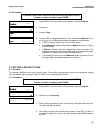
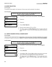
6.2 CALIBRATING TEMPERATURE
6.3 AUTO CALIBRATION - pH
6.4 MANUAL CALIBRATION - pH
6.5 STANDARDIZATION - pH
6.6 ENTERING A KNOWN SLOPE - pH
6.7 ORP CALIBRATION
6.8 CALIBRATING AN IN-SERVICE SENSOR - CONDUCTIVITY
6.9 PLACING A NEW SENSOR IN SERVICE - CONDUCTIVITY
6.10 CALIBRATING THE ANALYZER - CONDUCTIVITY
6.1 INTRODUCTION
The Calibrate Menu allows the user to calibrate sensor 1 (pH or ORP) and sensor 2 (conductivity). The tempera-
ture response of each sensor can also be calibrated.
For pH sensors, two-point buffer calibration is standard. In auto calibration the analyzer calculates the pH of the
buffer from the nominal value entered by the user and does not accept calibration data until readings are stable.
In manual calibration the user enters buffer values and judges when readings are stable. The pH reading can also
be standardized, that is, forced to match the reading from a referee instrument. Finally, if the user knows the elec-
trode slope (at 25°C), he can enter it directly.
The ORP calibration is a single-point calibration against an ORP standard.
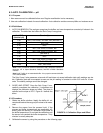
For conductivity measurements, several types of calibration are possible. The sensor and analyzer can be cali-
brated as a unit against a solution having an accurately known conductivity, or they can be calibrated against a
referee instrument. The analyzer and sensor can also be calibrated separately. The analyzer is calibrated against
a known resistance. The sensor cell constant can be measured independently and the results entered directly into
the Solu Comp II.