


30
MODEL SOLU COMP II SECTION 5.0
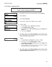
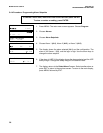
PROGRAMMING THE ANALYZER
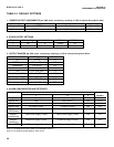
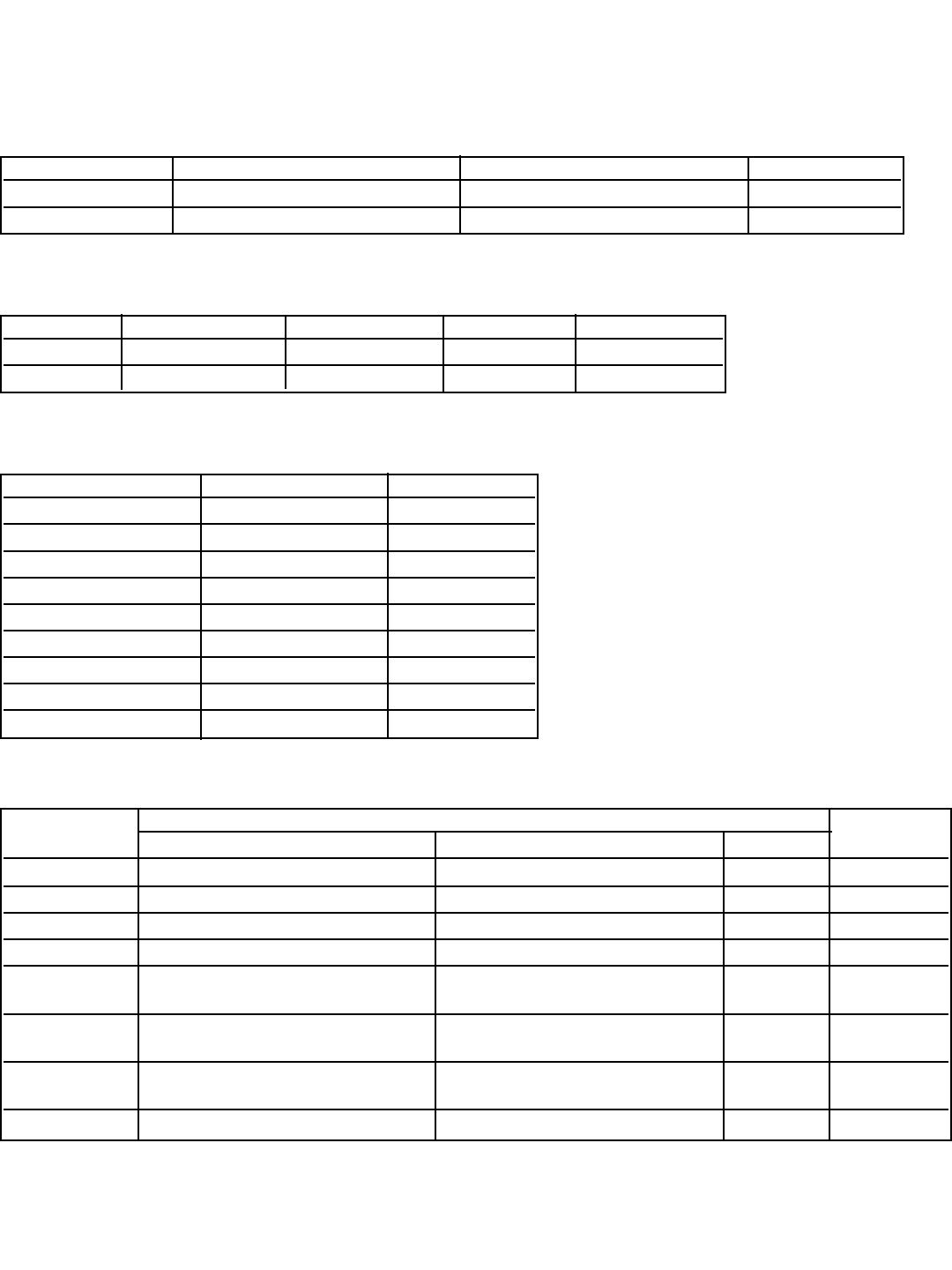
TABLE 5-1. DEFAULT SETTINGS
1. SENSOR-OUTPUT ASSIGNMENTS (pH, ORP, redox, conductivity, resistivity, or TDS is selected during Quick Start)
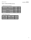
3. OUTPUT RANGES (pH, ORP, redox, conductivity, resistivity, or TDS is selected during Quick Start)
Measurement Range Section
pH 0 to 14 5.3
ORP/Redox -1400 to 1400 mV 5.3
Temperature 0 to 100°C 5.3
Resistivity 0.0 to 20 MΩ-cm 5.3
TDS 0 to 1000 ppm 5.3
Conductivity — 0.01/cm 0 to 10 µS/cm 5.3
Conductivity — 0.1/cm 0 to 100 µS/cm 5.3
Conductivity — 1.0/cm 0 to 1000 µS/cm 5.3
Conductivity — 10/cm 0 to 20 mS/cm 5.3
Sensor(s) Output 1 Output 2 Section
Single sensor pH/ORP/Redox Temperature 5.3 and 5.9
Dual sensor pH/ORP/Redox (sensor 1) Conductivity/Resistivity (sensor 2) 5.3 and 5.9
2. OTHER OUTPUT SETTINGS
Output Dampening 0 or 4 mA Mode Section
1 off 4 Linear 5.3
2 off 4 Linear 5.3
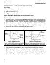
4. ALARM CONFIGURATION AND SETPOINTS
Alarm
1 2 3 Section
Assigned to Sensor 1 (pH, ORP) Sensor 2 (conductivity) (note 1) Fault 5.4
High or low High High (note 2) NA 5.4
Deadband 0 0 NA 5.4
Setpoint (pH) 14 (high); 0 (low) 14 (high); 0 (low) NA 5.4
Setpoint 1400 mV (high); -1400 (low) 1400 mV (high); -1400 (low) NA 5.4
(ORP/Redox)
Setpoint 1000 µS/cm (high); 0 (low) 1000 µS/cm (high); 0 (low) NA 5.4
(conductivity)
Setpoint 20 MΩ-cm (high); 0 (low) 20 MΩ-cm (high); 0 (low) NA 5.4
(resistivity)
Setpoint (TDS) 1000 ppm (high); 0 (low) 1000 ppm (high); 0 (low) NA 5.4
Note 1: For single sensor input, alarm 2 is assigned to sensor 1.
Note 2: For resistivity measurements, alarm is low.