


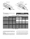
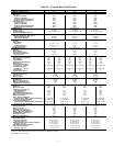
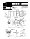
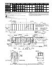
UNIT
MODEL
UNIT
SIZE
XY Z
mm ft-in. mm ft-in. mm ft-in.
48DJ,DK,NP 054,064
2474 8-1
3
⁄
8
8476 27-9
11
⁄
16
6965 22-10
3
⁄
16
50DW,DY,NB 054,064
50DJ,DK,NP 054,064 2458 8-0
3
⁄
4
7444 24-5
1
⁄
16
5933 19- 5
9
⁄
16
48DJ,DK,NP 074
3383 11-1
3
⁄
16
8476 27-9
11
⁄
16
6965 22-10
3
⁄
16
50DW,DY,NB 074
50DJ,DK,NP 074 3367 11-0
9
⁄
16
7444 24-5
1
⁄
16
5933 19- 5
9
⁄
16
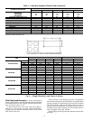
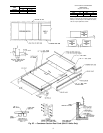
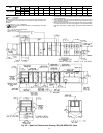
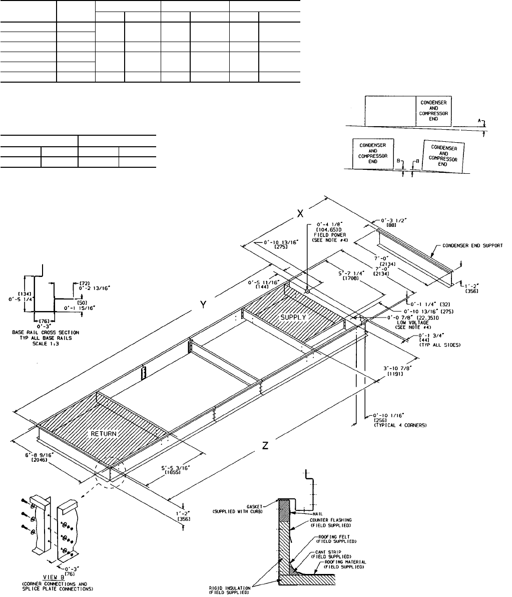
UNIT LEVELING TOLERANCES
DIMENSIONS*
(degrees and inches)
AB
Deg in. Deg in.
1.0 2.0 .50 .75
*From edge of unit to horizontal.
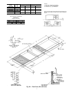
NOTES:
1. Roof curb is shipped unassembled.
2. Roof curb: 14 gage (VA03-56) steel.
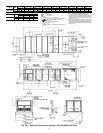
3. Dimensions in [ ] are millimeters.
4. Suggested hole location for field wiring
through roof curb (holes to be field drilled).
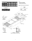
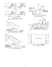
NOTE: Toprevent the hazardof stagnant water build-upin the
drain pan of the indoor-air section, unit can only be pitched as
shown.
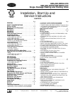
Fig. 3B — Roof Curb; 054-074 Units
8