


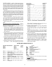
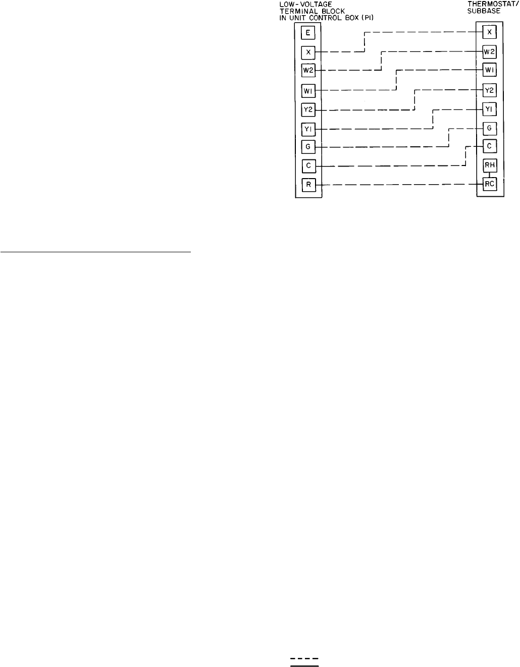
CONTROL WIRING — Install a Carrier-approved acces-
sory 24-v thermostat assembly according to the installation
instructions shipped with the accessory. Locate thermostat
assembly to sense averagetemperature. Route thermostat cable
or equivalent leads of colored wire from subbase terminals
to terminal board (P1). The terminal board (P1) is located on
the constant volume control board on units with no econo-
mizer and on the economizer board on units with the econo-
mizer option.
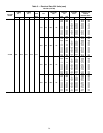
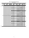
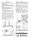
Total wire lengths should not exceed the following limits:
50 ft of 18 AWG, 80 ft of 16AWG or 125 ft of 14 AWG. See
Fig. 19 for field wiring connections between the thermostat
and the unit 24-v terminal block. Once wire length from unit
to thermostat is determined, the length should be doubled to
obtain total wire length required. Voltage drop is dependent
on length of current path.
There are no required 115-v field wiring connections, there-
fore no provisions have been made in the unit for running
115-v wiring. If any of the field-installed options requiring
115-v connections are desired, the unit must be modified in
the field for 115-v wiring.
Options requiring 24-v or 115-v control wiring are listed
below.
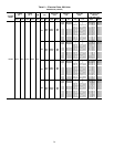
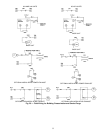
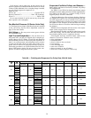
Building Pressurization or Smoke Purge Mode — Refer to
appropriate unit Controls and Troubleshooting literature as
necessary for additional information. See Fig. 20 and unit
wiring label for wiring details.
1. Firestat or smoke detector (field-supplied normally-
closed switch 1) — Remove factory-installed jumper wire
and wire a field-supplied firestat or smoke detector con-
tactor between terminals 5 and 6 (034-044 units) or ter-
minals 2 and 3 (054-074 units) on terminal block 2 in the
unit control box.
2. Switch to drive economizer outdoor-air damper fully open
(field-supplied normally-open switch 2) — Wire a field-
supplied switch between terminals 8 and 9 on econo-
mizer motor no. 1. When this switch is manually closed,
it will drive the outdoor-air damper fully open.
3. Switch to disconnect power to economizer motors (field-
supplied normally-closed switch 3) — Wire a field-
supplied switch between terminal C on the economizer
motor and Plug 8, Pin 2 (PL8-2).
4. Building pressurization switch (field-supplied normally-
open switch 4) — Wire a field-supplied switch between
TB2 and the C1 connection on the evaporator-fan con-
tactor coil (IFC on unit label diagram).
5. Switch to isolate evaporator-fan motor (field-supplied
normally-closed switch 5).
Modulating Power Exhaust —Wire afield-supplied switch
in series with the black wire removed from TRAN3
primary.
Constant Volume Power Exhaust — Wire a field-supplied
switch in series with the black wire from Plug 7, Pin 1
(PL7-1) to the red wire on economizer motor no. 2 (DMS1
on unit label diagram).
6. Switch to energize power exhaust motor (field-supplied
normally-open switch 6) — Wire a field-supplied switch
from terminal 5 (on 034-044 units) or terminal 2 (054-
074 units) on terminal block 2 in series with the red wire
from switch 5 to the damper motor switch (DMS1) on
economizer motor no. 2 (or in parallel with SW5).
7. Switch to fully open power exhaust damper (field-
supplied normally-open switch 7) — Wire a field-
supplied switch between terminal C and the normally-
closed switch on DPS2.
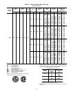
NOTES AND LEGEND FOR FIG. 20
BUILDING PRESSURIZATION SMOKE PURGE ALARM
Switch 1 Switch 1 Switch 1
Switch 2 Switch 2 Switch 3
Switch 4 Switch 5
Switch 5 Switch 6
Switch 7 (MPE)
Switch 1 — Remove jumper. Firestat or smoke detector —
normally closed.
Switch 2 — Switch to drive economizer outdoor-air damper fully
open — normally open.
Switch 3 — Switch to disconnect power to economizer motors.
Drives economizeroutdoor-air damperfully closed —
normally closed.
Switch 4 — Building pressurization switch (energize evaporator-
fan motor) — normally open.
Switch 5 — Switch to isolate evaporator-fan motor — normally
closed.
Switch 6 — Switchto energizepower exhaust motors— normally
open.
Switch 7 — Switch to fully open power exhaust damper —
normally open.
LEGEND
C—Contactor
DPS — Differential Pressure Switch
DMS — Damper Motor Switch
ECON — Economizer
IFC — Indoor (Evaporator) Fan Contactor
MPE — Modulating Power Exhaust
NC — Normally Closed
NO — Normally Open
PEC — Power Exhaust Contactor Coil
PL — Plug
SW — Switch
TB — Terminal Block
TRAN — Transformer
NOTES:
1. Power exhaust option can be unit mounted on vertical supply/
return units only.
2. is field wiring.
3. is field wiring.
4. Switches 1-7 are field supplied.
5. Forbuildingpressurization,field suppliedpowersource mustdrive
room terminals wide open.
Fig. 19 — Field Control Thermostat Wiring
34