


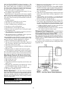

GAS VALVEADJUSTMENT (48 Series Units Only) — The
gas valve opens and closes in response to the thermostat or
limit control. When power is supplied to valve terminal 3
(D1 on low heat), the pilot valve opens to the preset posi-
tion. When power is supplied to terminal 2 (W1 on low heat),
the main valve opens to its preset position.
The regulator factory manifold pressure setting 2.9 in. wg
and is stamped on the valve body.
Manifold pressure is the pressure at the factory-supplied
pressure tap on the manifold downstream of the gas valve.
This is not the same as the pressure at the tap on the gas
valve body.Always use the tap on the manifold to read mani-
fold pressure.
To adjust regulator:
1. Set thermostat at setting for no call for heat.
2. Turn main gas valve to OFF position.
3. Install a suitable pressure measuring device.
4. Set main gas valve to ON position.
5. Set thermostat to call for high fire (W2).
6. Remove screw cap or plastic cover covering the regula-
tor adjustment screw.
7. Turn adjustment screw clockwise to increase pressure or
counterclockwise to decrease pressure.
8. Once desired pressure is established, remove pressure-
measuring device and replace screw cap.
MAIN BURNERS ADJUSTMENT (48 Series Units Only)
— Main burners are factory set and should require no ad-
justment. However, if burner adjustment is necessary:
1. Perform Automatic Pilot Adjustment (page 49).
2. Turn gas valve to ON position. Allow unit to operate at
least 15 minutes with heat section access panel closed.
3. Open heat section access panel.
4. Loosen primary air shutter and adjust to a minimum open-
ing of
5
⁄
8
inch.
5. Retighten primary air shutter and close access panel.
To check ignition of main burners and fan switch opera-
tion, move thermostat dial above and below room tempera-
ture several times, pausing at least one minutebetween cycles.
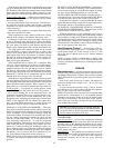
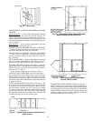
Main Burner Removal (48 Series Units Only)
NOTE: For high-heat units, the side posts must be removed
before the burner assembly can be removed.
1. Shut off main gas valve.
2. Shut off power to unit.
3. Unplug PL9 (and PL10 on high-heat) and all sensor and
ignitor wires.
4. Disconnect gas connection(s) from between gas valve(s)
and field-supplied piping. See Fig. 37 and 38.
5. Remove 2 screws securing burner assembly to unit.
6. Slide burner assembly from unit.
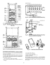
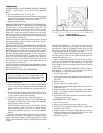
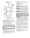
Switch Adjustment — All units with an economizer
have an auxiliary switch located on the economizer damper
motor. This switch is factory set to prevent the power ex-
haust from operating when the economizer damper is less
than 50% open. If other than the factory setting is desired,
follow the steps below.
Do not turn motor shaft by hand or with a wrench. Dam-
age to the gear train will result.
1. Remove top cover from motor to gain access to motor
terminals and cam adjustments.
2. Disconnect controller from motor. Connect RED, WHITE,
and BLUE terminals on the 135-ohm manual potentiom-
eter to corresponding RED, WHITE, and BLUE termi-
nals on the motor. Connect 24-vac power to Terminals 1
and 2. See Fig. 60.
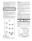
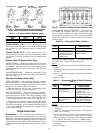
3. Adjust the 135-ohm potentiometer so that the motor shaft
turns to the position where auxiliary equipment is to be
switched.
4. Adjust auxiliary cam by inserting a
1
⁄
8
-in. straight blade
screwdriver into slot on cam and moving TOP of screw-
driver to the right or left. See Fig. 61.
5. To close auxiliary switch RED and BLUE contacts as the
motor travels open (energizing the power exhaust mo-
tor), the switch differential can only be 10 degrees on both
switches. To adjusteither cam, perform the following steps:
a. If RED and BLUE contacts are open, rotate the cam
counterclockwise until the contacts close.
b. If the RED and BLUE contacts are closed, rotate the
cam clockwise until the contacts open.
Refrigerant Feed Components — Each refrigerant
circuit (2 per unit) has all the necessary refrigerant controls.
Thermostatic Expansion Valve (TXV) — On size
034, each circuit has one. On size 044, each circuit has 2.
The superheat is nonadjustable. On sizes 054-074, each cir-
cuit has 2 TXVs on which superheat may be adjusted if ab-
solutely necessary.
The TXV is set to maintain 10 to 13 F superheat leaving
the evaporator coil. It controls the flow of refrigerant to the
evaporator coils.
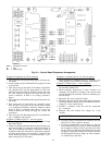
Fig. 60 — Auxiliary Switch Stroke Adjustment
50