


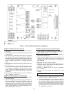
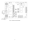
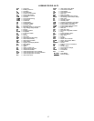
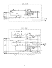
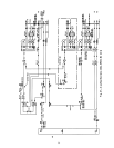
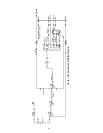
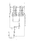
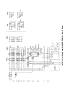
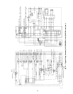
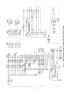

LEGEND FOR FIG. 66-73
ACC — Accessory
BP — Building Pressure
C—Contactor
CB — Circuit Breaker
CCB — Control Circuit Breaker
CF — Check Filter Switch
CLO — Compressor Lockout
COM — Common
COMM — Communication Plug
COMP — Compressor
COND — Condenser
CR — Control Relay
CS — Centrifugal Switch
CV — Constant Volume
DP — Duct Pressure
DPT — Discharge Pressure Transducer
DSIO — High-Voltage Relay Module
DU — Dummy
EC — Enthalpy Control
EQUIP — Equipment
FS — Fan Status Switch
FU — Fuse
GND — Ground
GR — Gas Relay
HHR — Hydronic Humidifier Relay
HIR — Heat Interlock Relay
HPS — High-Pressure Switch
HR — Heater Relay
HSIO — Keypad and Display Module
HV — High Voltage
HYD — Hydronic
I—Ignitor
ICP — Ignitor Control Pack
IDC — Induced Draft Contactor
IDM — Induced Draft Motor
IFC — Indoor (Evaporator) Fan Contactor
IFCB — Indoor (Evaporator) Fan Circuit Breaker
IFM — Indoor (Evaporator) Fan Motor
IGV — Inlet Guide Vanes
IGVM — Inlet Guide Vanes Motor
LPS — Low-Pressure Switch
LS — Limit Switch
LSR — Limit Switch Relay
MG — Main Gas
MGV — Main Gas Valve
MM — Head Control Pressure Device
MPER — Modulating Power Exhaust Relay
MV — Main Valve
NC — Normally Closed
NO — Normally Open
OFM — Outdoor (Condenser) Fan Motor
PCB — Power Exhaust Circuit Breaker
PEC — Power Exhaust Contactor
PEDM — Power Exhaust Damper Motor
PEM — Power Exhaust Motor
PG — Pilot Gas
PGV — Pilot Gas Valve
PIC — Processor-Integrated Controls
P, PL — Plug
PS — Power Supply (5 VDC)
PSIO — Processor Module
PV — Pilot Valve
PWR — Power
RES — Resistor
RFC — Return Fan Contactor
RFDM — Return Fan Damper Motor
RS — Rollout Switch
SEN,SN — Sensor
SPT — Suction Pressure Transducer
SW — Switch
TB — Terminal Block
TDO — Timed Discrete Output
TH — Thermostat
TRAN — Transformer
VLV — Valve
Field Wiring
Factory Wiring
57