


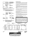


POWER WIRING — Units are factory wired for the voltage
shown on the unit nameplate. The main terminal block is
suitable for use with aluminum or copper wires. Maximum
wire size is 3/0 AWG (American Wire Gage).
When installing units, provide a disconnect per NEC
(National Electrical Code) of adequate size (MOCP [Maxi-
mum Overcurrent Protection] of unit is on the informative
plate). All field wiring must comply with NEC and all local
codes. Size wire based on MCA (Minimum Circuit Amps)
on the unit informative plate. See Fig. 18 for power wiring
connections to the unit power terminal block and equipment
ground.
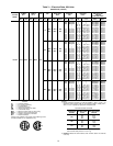
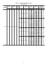
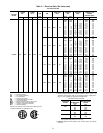
Operating voltage to the compressor must be within the
voltage range indicated on the unit nameplate. Voltages be-
tween phases must be balanced within 2%, and the current
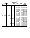
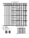
must be balanced within 10%. See Tables 3-7 for unit elec-
trical data.
Use the following formula to determine the percent
voltage imbalance.
% Voltage Imbalance
max voltage deviation from average voltage
= 100 x
average voltage
Example: Supply voltage is 460-3-60.
AB = 452 v
BC = 464 v
AC = 455 v
452 ϩ 464 ϩ 455
Average Voltage =
3
1371
=
3
457
=
Determine maximum deviation from average voltage:
(AB) 457 – 452=5v
(BC) 464 – 457=7v
(AC) 457 – 455=2v
Maximum deviation is 7 v.
Determine percent voltage imbalance:
7
% Voltage Imbalance = 100 x
457
= 1.53%
This amount of phase imbalance is satisfactory as it is be-
low the maximum allowable 2%.
IMPORTANT: If the supply voltage phase imbalance
is more than 2%, contact local utility immediately.
Unit failure as a result of operation on improper line volt-
age or excessive phase imbalance constitutes abuse and may
cause damage to electrical components.
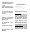
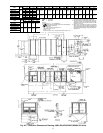
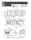
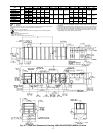
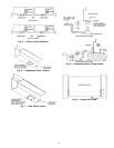
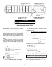
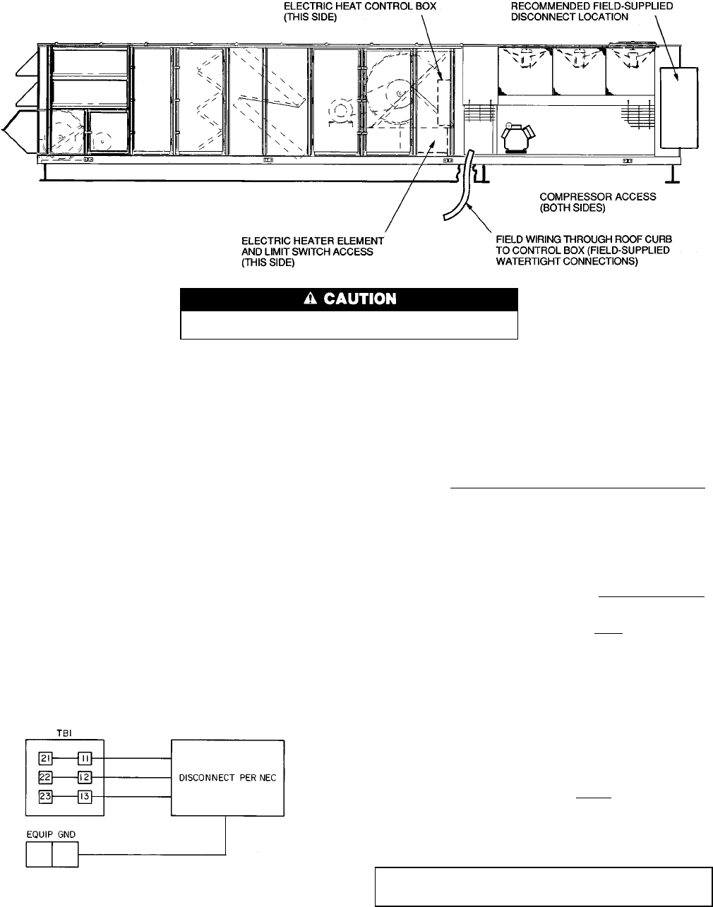
Use care when drilling into corner post to avoid damage to con-
denser coil.
Fig. 17 — Disconnect Location, 054-074 Units
(50 Series Horizontal Discharge Shown)
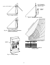
LEGEND
EQUIP — Equipment
GND — Ground
NEC — National Electrical Code
TB — Terminal Block
Fig. 18 — Field Power Wiring Connections
18