


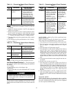

Table 14 — Economizer Control Board Checkout,
Test 2
MOTOR
TEST
PROCEDURE EXPECTED RESULT
AND RESPONSE
A Turn enthalpy set point
potentiometer to the
A position.
1. The relays energize. If not,
check return enthalpy re-
sistor. If resistor is o.k.,
control board is faulty.
2. Motor drives open. If re-
lays energize, but motor
does not drive open, the
control board is faulty.
B Turn enthalpy set point
potentiometer to the
D position.
1. The relays deenergize. If
not, control board is faulty.
2. Motor drives closed. If re-
lays deenergize by motor
does not drive closed, the
control board is faulty.
Test 3:
1. Apply 24 VAC power to terminals T0 and T2 of the con-
trol board.
2. Apply 24 v between terminals 1 and T2, and jumper ter-
minal T0 to terminal 1.
3. Remove the mixed-air sensor connected between termi-
nals S1 and S2, and replace it with a 5490-ohm resistor.
4. Remove outdoor-air enthalpy sensor between terminals
ϩϩ and SO, and replace it with a 1.2 kOhm resistor.
5. Turn the minimum position potentiometer fully counter-
clockwise.
6. Turn enthalpy set point potentiometer to the A setting.
7. Refer to Table 15.
Table 15 — Economizer Control Board Checkout,
Test 3
MOTOR
TEST
PROCEDURE EXPECTED RESULT
AND RESPONSE
A Turn mixed-air potenti-
ometer to the midpoint
position.
Motor should drive to mid-
stroke with the set point set
between 60 and 70 F. If not,
the control board is faulty.
B Turn mixed-air
potentiometer fully
counterclockwise.
Motor drives open, If not, the
control board is faulty.
C Turn mixed-air potenti-
ometer fully clockwise.
Motor drives closed. If not,
the control board is faulty.
Test 4
Refer to Table 16 for the correct procedure for test 4.
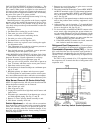
Unit Control Board Checkout — The following tools
are required to perform the troubleshooting tasks detailed in
this section:
• 1.5-v battery
• 2 sets of jumper wires with alligator clips
• Multimeter
• Toggle switch with 14-in. wires terminated with
1
⁄
4
-in. spade
connectors
Read these instructions completely before attempting to
troubleshoot the control board. Failure to follow the steps
precisely could result in damage to unit, personal in-
jury, or death.
The control board checkout procedure consists of 2 parts:
A basic check to verify availability of 24 and 115 v to the
control board and a detailed check of each circuit within the
board.
Table 16 — Economizer Control Board Checkout,
Test 4
MOTOR
TEST
PROCEDURE EXPECTEDRESULT
AND RESPONSE
A (Outdoor-
Air Sensor)
1. Connect the enthalpy
sensor terminal ϩ to
terminal ϩ on the motor.
2. Connect the positive ter-
minal of a DC milliam-
meter to terminal S of
the sensor.
3. Connect the negative
terminal of a DC milliam-
meter to terminal S
O
of
the enthalpy board.
Milliammeter reading
should be between
3 and 24 mA if the
sensor is operating
correctly. If the read-
ing is 0 mA, the
sensor is either
wired backward or is
defective.
B (Indoor-
Air Sensor)
1. Connect the enthalpy
sensor terminal ϩ to
terminal ϩ on the motor.
2. Connect the positive ter-
minal of a DC milliam-
meter to terminal S of
the sensor.
3. Connect the negative
terminal of a DC milliam-
meter to terminal S
R
of
the enthalpy board.
Milliammeter reading
should be between
3 and 24 mA if the
sensor is operating
correctly. If the read-
ing is 0 mA, the
sensor is either
wired backward or is
defective.
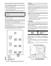
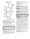
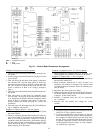
BASIC CHECK — Refer to Fig. 64 for control board com-
ponent identification.
NOTE: All plugs (except P1) are labeled for easy identifi-
cation. Plug P1 can be identified by its orange color.
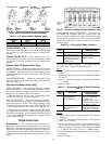
1. Turn unit poweroff. Disconnect plugP1 from control board.
2. Turn unit power on and check voltage across Pin R and
Pin C at plug P1. If voltage reads 18 to 30 v, skip to
Step 5.
3. Turn unit power off. Disconnect plug P3.
4. Turn unit power on and measure voltage across wires on
plug P3, Pins 1 and 2 (wires coming from the unit). If
voltage reads 18 to 30 v, there is either a bad connection
between plug P3 and control board, or the control board
is defective. Verify the connection at this point and pro-
ceed to Step 5. If there is no voltage, check the circuit
breaker and transformer in the 24-v control circuit of the
unit.
5. Turn unit power off and disconnect plug P4 from the con-
trol board.
6. Switch scale on meter to read 115 v.
7. Turn unit power on and check voltage across Pin 6 on
plug 4 and unit ground (wires coming from the unit). If
voltage reads 104 to 122 v, there is adequate power avail-
able to the board. Verify connection at this point and pro-
ceed to Step 8. If there is no voltage, check the circuit
breaker and transformer in the 115-v control circuit of
the unit.
8. After verifying that 24-v and 115-v supply power is avail-
able to the control board, turn unit power off and recon-
nect plugs P1,P3, and P4.Proceed to Detailed Checksection
below.
DETAILED CHECK
NOTE: Plug P1 must be disconnected in order to perform
any of the troubleshooting steps detailed in this section. To
save time, reconnect plug P1 only after you have completed
all of the required troubleshooting.
53