


When the first-stage thermostat is satisfied, first-stage main
gas valve and the pilot valve close. Induced-draft motor shuts
off. Time-delay relay (builtinto constant volume control board)
opens and timer sequence begins. When sequence is com-
plete (after 110 ± 5 seconds) evaporator-fan motor shuts off.
48 Series High-Heat Units — Unit power on, thermostat sys-
tem switch set at HEAT or AUTO. position, and fan switch
set at AUTO. position.
First-stage thermostat (W1) calls for heat. Time-delay re-
lay (built into constant volume control board), controlling
evaporator fan, begins timer sequence (approximately 55 ±
10-second delay).
When time-delay sequence is complete, time-delay relay
closes and evaporator fan starts.
When evaporator fan starts, airflow switch closes, closing
induced draft contactor, and induced draft motor starts.
Centrifugal switch closes. Pilot valve opens, allowing gas
to flow to first-stage pilot. Spark ignitor ignites pilot flame.
Sensor detects flame, energizes main gas valve coil, and main
gas valve opens. Gas flows to main burners and first-stage
burners ignite. Spark ignitor shuts off and pilot remains on.
The spark ignitor will continue to spark for 90 seconds
until pilot flame is sensed. If the pilot fails to ignite or the
sensor fails to detect flame, the pilot valve closes and the
spark ignitor shuts off for 300 seconds (5 minutes). During
this time the induced draft motor remains on to purge any
unburnt gas from the combustion tubes. This ignition se-
quence will repeat indefinitely.
When additional heat is needed, W2 is energized. Pilot
valve no. 2 opens, allowing gas to flow to second-stage pi-
lot. Spark ignitor ignites pilot flame. Sensor detects flame,
energizes main gas valve coil, and maingas valve no. 2 opens.
Gas flows to main burners and second-stage burners ignite.
Second-stage spark ignitor shuts off. When the second-stage
thermostat is satisfied, W2 is deenergized and the second
induced-draft motor and gas valve are shut off.
When the first-stage thermostat is satisfied, first-stage main
gas valve and the pilot valve close. Induced draft motor shuts
off. Time-delay relay (builtinto constant volume control board)
opens and timer sequence begins. When sequence is com-
plete (after 110 ± 5 seconds) evaporator-fan motor shuts off.
50 Series Units — Unit power on, system selector switch
set at HEAT position, fan switch set at AUTO. position.
On a call for heating, W1 on the thermostat closes, and
evaporator fan and the first stage of electric heat are ener-
gized. On a further drop in room temperature, W2 on the
thermostat closes, energizing the second stage ofelectric heat.
NOTE: Units equipped with low electric heat option have
only one stage. Reset thermostat to a setting below room
temperature. Electric heat and evaporator fan shut off.
COOLING, UNITS WITH ECONOMIZER — With sub-
base switch set at COOLposition and fan switch set at AUTO.
position, evaporator fan is energized when Y1 on thermostat
closes. If enthalpy is below setting on enthalpy switch, the
economizer outdoor-air dampers will modulate open to sat-
isfy the cooling requirement. If outdoor air alone will not
meet the cooling requirements, Y2 on the thermostat will
close energizing compressor no. 1 to work in conjunction
with the modulating economizer to meet the cooling require-
ment. While the unit is operating using outdoor air, com-
pressor no. 2 cannot be energized. If enthalpy is above set-
ting on enthalpy switch, the economizer outdoor-air dampers
move to the minimum (ventilation) position, and condenser
fan numbers 1 and 2 cycle on and off as described in Cool-
ing, Units Without Economizer section on page 41.
NOTE: If fan switch is ON position and the room thermostat
is satisfied, the outdoor-air dampers move to the minimum
position.
HEATING, UNITS WITH ECONOMIZER — Operation is
the same as described in Heating, Units Without Econo-
mizer sections on page 41, except that the outdoor-air damp-
ers move to the minimum position on a call for heat.
VENTILATION-AIR CIRCULATION (Continuous Fan) —
Turn unit power on. Set system selector switch at OFF,HEAT,
or COOL position, and set fan switch at ON position.
Evaporator-fan contactor is energized through the switch
on the thermostat and the evaporator fan runs continuously.
The damper moves to the minimum position.
AUTOMATIC CHANGEOVER USING AUTOMATIC
CHANGEOVER THERMOSTAT —Turn unit power on. Set
system selector switch at AUTO. position.
When the temperature of the conditioned space rises to
the cooling selector lever setting, unit automatically switches
from heating to cooling mode. When the temperature of the
conditioned space falls to the heating selector switch setting,
unit automatically changes from cooling to heating mode.
The thermostat is interlocked so that cooling and heating sys-
tems do not operate at the same time.
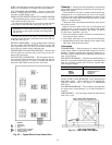
Head Pressure Control — All units have a fan cy-
cling thermostat which cycles the no. 2 condenser fan. This
switch opens at 60F±3°Fandcloses at 70F±3°F.This
allows the unit to operate down to 45 F outdoor ambient
temperature.
NOTE:Accessory −20 F LowAmbient Kit is available, which
allows mechanical cooling to −20 F outdoor ambient. See
accessory installation instructions for mounting and opera-
tion details.
SERVICE
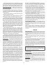
Service Access —
All unit components can be reached
through clearly labeled hinged access doors. These doors are
not equipped withtiebacks, so ifheavy duty servicing isneeded,
either remove them or prop them open to prevent accidental
closure.
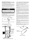
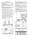
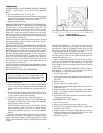
Each door is held closed with 3 latches. The latches are
secured to the unit with a single 1/4-in. Ϫ20 x 1/2-in. long
bolt. See Fig. 33.
To open, loosen the latch bolt using a 7/16-in. wrench.
Pivot the latch so it is not in contact with the door. Open the
door. To shut, reverse the above procedure.
NOTE: Disassembly of the top cover may be required under
special service circumstances. It is very important that the
orientation and position of the top cover be marked on the
unit prior to disassembly. This will allow proper replace-
ment of the top cover onto the unit and prevent rainwater
from leaking into the unit.
IMPORTANT:After servicing is completed, make sure
door is closed andrelatched properly, and that the latches
are tight. Failure to do this can result in water leakage
into the indoor-air section of the unit.
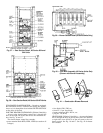
COMPRESSORS
Sizes 034 and 044 —Access to the compressors is through
the doors on the condenser end of the unit. This door also
provides access to the discharge and suction service valves,
the crankcase heaters, andthe high- and low-pressure switches.
Compressor no. 1 is always the compressor on the left when
facing main control box.
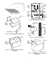
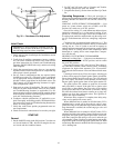
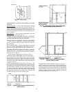
Sizes 054-074 — The oil pump end (compressor access) of
each compressor is readily accessible from sides of unit as
shown in Fig. 17. Access the motor end of the compressor
through the condenser end of the unit or by removing
compressor.
42