


CONTENTS (cont)
• AUTOMATIC PILOT ADJUSTMENT (48 Series
Units Only)
• GAS VALVE ADJUSTMENT (48 Series Units Only)
• MAIN BURNER ADJUSTMENT (48 Series
Units Only)
Main Burner Removal (48 Series Units Only) ..50
Switch Adjustment .........................50
Refrigerant Feed Components ...............50
Thermostatic Expansion Valve (TXV) .........50
Moisture/Liquid Indicator ....................51
Filter Drier ..................................51
Liquid Line Service Valve ....................51
Compressor Discharge Service Valve ........51
Compressor Suction Service Valve ...........51
Protective Devices ..........................51
• COMPRESSOR PROTECTION
• EVAPORATOR-FAN MOTOR PROTECTION
• CONDENSER-FAN MOTOR PROTECTION
• HIGH- AND LOW-PRESSURE SWITCHES
Relief Devices ..............................51
Control Circuit, 115 V .......................52
Control Circuit, 24 v .........................52
Electric Heat (50 Series Units Only) ..........52
• OVERCURRENT
• OVERTEMPERATURE
Gas Heat (48 Series Units Only) ..............52
• LIMIT SWITCHES
• ROLLOUT SWITCH
TROUBLESHOOTING ......................52-69
Economizer .................................52
• ECONOMIZER MOTOR CHECKOUT
• ECONOMIZER CONTROL BOARD CHECKOUT
Unit Control Board Checkout ................53
• BASIC CHECK
• DETAILED CHECK
START-UP CHECKLIST .....................CL-1
GENERAL
This installation instruction contains base unit installa-
tion, start-up, and service instructions only. For complete in-
formation on PIC (Product Integrated Controls) and variable-
air volume (VAV) controls and troubleshooting, refer to
appropriate Controls and Troubleshooting literature also en-
closed in this literature packet.
SAFETY CONSIDERATIONS
Installation and servicing of air-conditioning equipment
can be hazardous due to system pressure and electrical com-
ponents. Only trained and qualified service personnel should
install, repair, or service air-conditioning equipment.
Untrained personnel can perform basic maintenance func-
tions of cleaning coils and filters and replacing filters. All
other operations should be performed by trained service per-
sonnel. When working on air-conditioning equipment, ob-
serve precautions in the literature, tags and labels attached
to the unit, and other safety precautions that may apply.
Follow all safety codes, including ANSI (American Na-
tional Standards Institute) Z223.1. Wear safety glasses and
work gloves. Use quenching cloth for unbrazing operations.
Have fire extinguisher available for all brazing operations.
Before performing service or maintenance operations on
unit, turn off main power switch to unit. Electrical shock
could cause personal injury.
Do not try to light any appliance. Do not touch any elec-
trical switch; do not use any phone in your building.
Immediately call your gas supplier from a neighbor’s
phone. Follow the gas supplier’s instructions. If you can-
not reach your gas supplier, call the fire department.
Do not store or use gasoline or other flammable vapors
and liquids in the vicinity of this or any other appliance.
Improper installation, adjustment, alteration, service, or
maintenance can cause injury or property damage. Re-
fer to this manual. For assistance or additional infor-
mation, consult a qualified installer, service agency, or
the gas supplier.
Disconnect gas piping from 48 Series units when leak
testing at pressures greater than 0.5 psig. Pressures greater
than 0.5 psig will cause gas valve damage resulting in
a hazardous condition. If gas valve is subjected to pres-
sure greater than 0.5 psig, it must be replaced. When
pressure testing field-supplied gas piping at pressures of
0.5 psig or less, the unit connected to such piping must
be isolated by manually closing the gas valve.
INSTALLATION
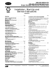
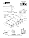
Rigging and Unit Placement —
Inspect unit for trans-
portation damage. File claim with transportation agency. Do
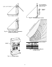
not drop unit; keep upright. Use spreader bars over unit to
prevent sling or cable damage. Sheets ofplywood placed along
the condenser coils will provide additional protection. All
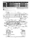
lifting lugs MUST be used when lifting unit. Level by using
unit frame as a reference. See Fig. 1 for information. Unit
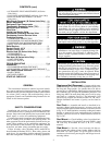
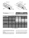
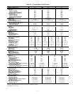
and accessory weights are shown in Tables 1A, 1B, and 2.
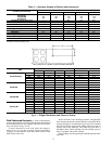
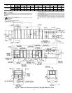
Weight distribution and center of gravity can be found in
Fig. 2.
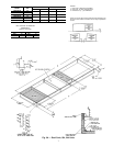
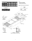
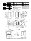
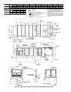
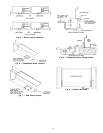
Roof Curb — Assemble and install as described in in-
structions shipped with the accessory. Accessory roof curb
and information required to field fabricatea roof curb is shown
in Fig. 3A-3C.Install insulation, cant strips,roofing and counter
flashing as required. For unit condensate drains to function
properly, curb must be level or within tolerances shown in
Fig. 3A-3C.
Roof Mount — Check building codes for weight distri-
bution requirements. Unit weight is shown in Tables 1A and
1B. Unit may be mounted on class A, B, or C roofing
material.
Slab Mount — Provide a level concrete slab that ex-
tends beyond unit cabinet at least 6 inches. Make a slab 8 in.
thick with 4 in. above grade. Use gravel apron in front of
condenser coil air inlet to prevent grass and foliage from ob-
structing airflow.
2