


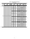
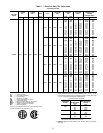
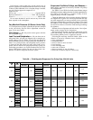
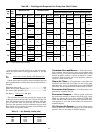
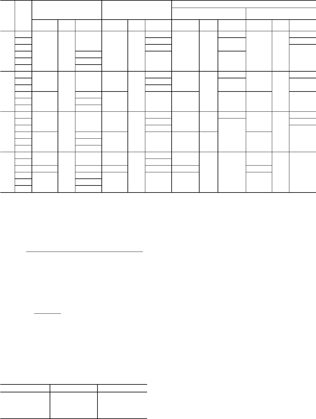
Table 9B — Field-Supplied Evaporator-Fan Pulley Data, 054-074 Units
IFM
Hp
IFM
RPM
MOTOR PULLEY BLOWER PULLEY
BELTS
48 Series and 50 Series
Horizontal Discharge Units
50 Series
Vertical Discharge Units
No.
Grooves
Type Size (in.)
No.
Grooves
Type Size (in.) Quantity Type Size (in.) Quantity Type Size (in.)
15
450
2 B5V
4.3
2 B5V
18.5
2 5VX
118
2 5VX
132
470 16.1
115
125
485 15.5
123
575 4.5
13.7 112650 5.1
725 5.7
20
405
3
B5V
4.3 3
B5V
18.5
3
5VX
123
3
5VX
132
470 16.1
118 125
485 15.5
575
2
4.5
2 13.7 2 115 2 123660 5.1
725 5.7
25
405
3
B5V
4.3 3
B5V
18.5
3 5VX
123
3
5VX
132
470 16.1
115
125
485 15.5
123
575
2
4.5
2 13.7 2 B5V 2700 5.5
725 5.7
30
470
4
B5V
4.3 4
B5V
16.1
4
5VX 118
4
5VX 123
485 15.5
530 3 4.7 3 15.5 3 3
600
2
5.5
2 15.5 2 2660 5.9
730 6.5
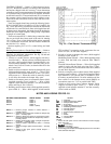
IFM — Indoor (Evaporator) Fan Motor
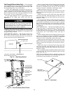
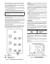
Check rotation of wheel with arrow on the fan housing.
Check fan speed with a strobe-type tachometer, or use this
formula:
motor rpm x motor sheave pitch diameter (in.)
Fan
=
Rpm
fan sheave pitch diameter (in.)
(Obtain motor rpm from the fan motor nameplate and read
sheave pitch diameters marked on the fan and motor sheaves.)
Example:
Nameplate motor rpm .................................................. 1760
Motor sheave pitch diameter (in.) .................................. 6.4
Fan sheave pitch diameter (in.) .................................... 12.4
1760 x 6.4
Fan Rpm = = 908 Rpm
12.4
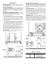
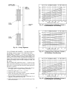
The maximum allowable fan speed for the supply-air fan
is 900 rpm for 034 and 044 units and 750 rpm for 054-074
units. The maximum rpm for the power exhaust is 1300 rpm
for 034 and 044 units and 925 rpm for 054-074 units.
Excessive fan speed may result in condensate carryover from
the evaporator coil, fan motor overload, or wheel failure. See
Table 10 for Air Quantity Limits.
Table 10 — Air Quantity Limits (cfm)
UNIT SIZE MINIMUM MAXIMUM
034 6,000 15,000
044 8,000 20,000
054 10,000 25,000
064 12,000 30,000
074 14,000 30,000
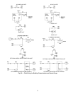
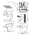
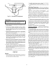
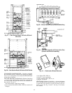
Condenser Fans and Motors — Each unit has mul-
tiple condenser fans and motors; these are positioned at the
factory. See Fig. 32 for correct location of fan inorifice. Check
that fan propeller rotation is correct; it should be counter-
clockwise when facing the fans. If fan propeller rotation is
incorrect, switch motor leads.
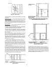
Return-Air Filters — Check that the correct filters are
installed in the filter rack. See Tables 1A and 1B for quan-
tities and sizes. Access is through the door marked FILTER
SECTION. Do not operate the unit without return-air filters.
Economizer Inlet Screens — Check that they are in
place before operating the unit.
Economizer Dampers — With no power to the unit,
the economizer outdoor-air dampers should be fully closed.
Check by opening the access door marked FILTER SEC-
TION. On units with economizer, be sure economizer mini-
mum position is set at the desired setting. Be sure hood is
installed properly.
25% Outdoor-Air Damper — On units without econo-
mizer, be sure 25% outdoor-air damper is set at the desired
position. Also, be sure hood is installed properly.
40