


Adjustments
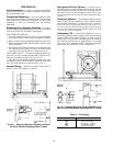
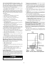
EVAPORATOR FAN AND POWER EXHAUST MOTOR
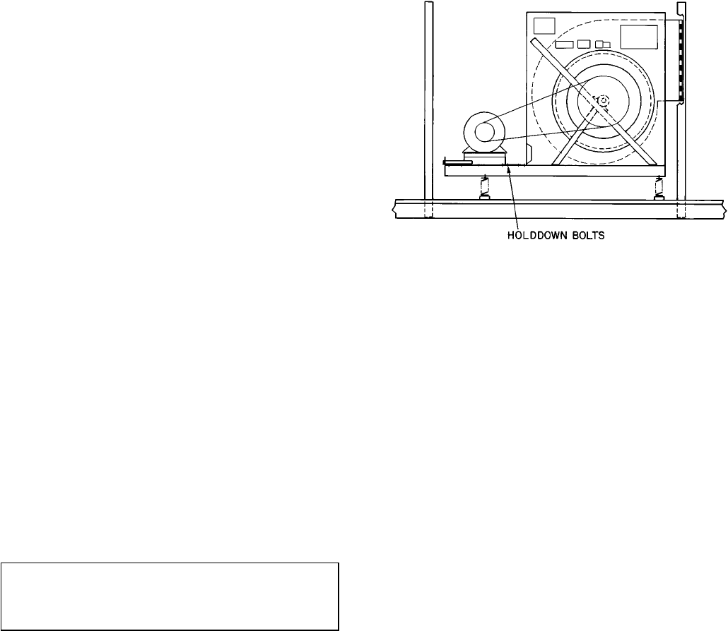
PLATE — Adjust using a
15
⁄
16
-in. wrench on the adjusting
bolts:
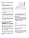
1. Loosen holddown bolts. (See Fig. 44.)
2. Turn the adjusting bolts to move the motor mounting plate
toward or away from the fan to loosen or tighten the belts.
Make the same number of turns to each bolt.
3. Retighten holddown bolts.
MODULATING POWER EXHAUST DIFFERENTIAL
PRESSURE SWITCH — On 034,044 units, the differential
pressure switch is located in the auxiliary control box. The
auxiliary control box is mounted in the corner next to the
power exhaust motor door. To gain access to the auxiliary
control box, remove the auxiliary control box cover. When
replacing the auxiliary control box cover, be sure to secure
the cover properly in order to prevent water from being drawn
into the auxiliary control box.
On 054-074 units, the differential pressure switch is mounted
below the auxiliary control box next to the access door la-
beled FILTER SECTION.
INLET GUIDE VANE DIFFERENTIAL PRESSURE
SWITCH (Units With Optional Inlet Guide Vanes and Static
Pressure Control) — On 034,044 units, the inlet guide vane
differential pressure switch is located in the auxiliary control
box. The auxiliary control box is mounted in the corner of
the unit under the side air hood that is next to the access
door marked FILTER SECTION. To gain access to the aux-
iliary box, remove the auxiliary control box cover. When re-
placing the auxiliary control box cover, be sure to secure the
cover properly in order to prevent water from being drawn
into the auxiliary control box.
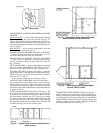
On 054-074 units, the inlet guide vane differential pressure
switch is mounted onan upright located behind the evaporator-
fan motor. See Fig. 43.
BELT INSTALLATION AND TENSIONING
IMPORTANT: When installing or replacing belts, al-
ways use a complete set of new, matched belts to pre-
vent potential vibration problems. Mixing belts often
results in premature breakage of the new belts.
1. Turn off unit power.
2. Adjust motor plate so belts can be installed without stretch-
ing over the grooves of the pulley. (Forcing the belts can
result in uneven belt stretching and a mismatched set of
belts.)
3. Before tensioning the belts, equalize belt slack so that it
is on the same side of the belt for all belts. Failure to do
so may result in uneven belt stretching.
4. Tighten belts using the motor plate adjusting bolts.
5. Adjust until proper belt tension (1/2-in. deflection with
one finger) is obtained. Be sure to adjust both adjusting
bolts the same number of turns.
NOTE: Check the tension at least twice during the first
day of operation, as there is normally a rapid decrease in
tension until the belts have run in. Check tension
periodically thereafter and keep it at the recommended
tension.
With the correct belt tension, belts may slip and squeal
momentarily on start-up. This slippage is normal and dis-
appears after wheel reaches operating speed. Excessive belt
tension shortens belt life and may cause bearing and shaft
damage.
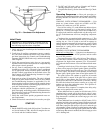
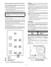
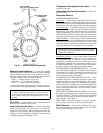
PULLEY ALIGNMENT — For proper belt life, the motor
and fan pulleys must be properly aligned. To check, first turn
off unit power. Place a straightedge against the motor and
fan pulleys. See Fig. 45. If the pulleys are properly aligned,
the straightedge should be parallel to the belts.
If they are not parallel, check that the motor shaft and fan
shaft are parallel. If they are not, adjust the motor plate ad-
justing bolts until they are.
After verifying that the shafts are parallel, loosen the set-
screws on the motor pulley. Move pulley on the shaft until
the pulleys are parallel. To move the sheave on the shaft,
loosen the belts. Ifnecessary, blowersheave can also be moved
on the shaft.
INSTALLING ALTERNATE MOTOR PULLEY (Evapora-
tor Fan Only) — On all units, the alternate motor pulley is
field-supplied. To install the alternate pulley:
1. Turn off unit power.
2. Loosen belts using motor adjusting bolts until belts can
be removed without stretching them over the grooves of
the pulley.
3. Remove belts.
4. Loosen setscrews on motor pulley.
5. Slide pulley off motor shaft. Make sure setscrews on new
pulley are loose.
6. Slide new pulley onto fan shaft and align it with the fan
pulley as described in Pulley Alignment section above.
7. Tighten setscrews.
8. Install belts and tension properly as described in Pulley
Alignment section above.
CONDENSER FAN ADJUSTMENT
1. Turn off unit power.
2. Remove fan guard and loosen fan hub setscrew.
3. See Fig. 32 and adjust fan height using a straight edge
laid across the fan deck.
4. Tighten setscrew and replace rubber hubcap to prevent
hub from rusting to the motor shaft. Fill hub recess with
Permagum if hub has no rubber hubcap.
5. Replace fan guard.
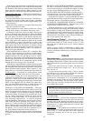
Fig. 44 — Motor Plate Adjustment
46