PRE-START-UP
Unit Preparation —
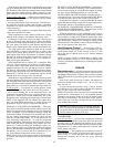
Check to see that unit has been
installed in accordance with these Installation Instructions
and all applicable codes.
Compressor Mounting — Loosen compressor hold-
down bolts until sidewise movement of the washer under
each holddown bolt head can be obtained. Do not loosen
completely, as bolts are self-locking and will maintain
adjustment.
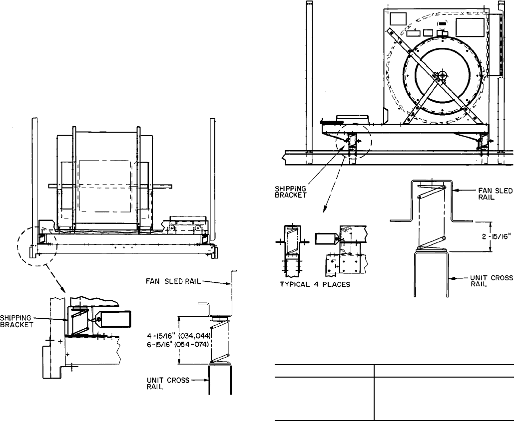
Evaporator-Fan Shipping Brackets — Evapor-
ator-fan shipping brackets (4 per unit) must be removed from
each corner of the fan sled before starting unit.
UNIT SIZES 034 AND 044
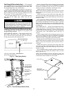
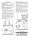
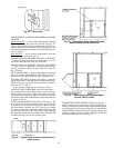
1. To remove brackets, raise fan sled by turning adjusting
bolt counterclockwise until spring is compressed slightly.
2. Remove screws holding shipping bracket to unit cross rail.
3. Remove shipping bracket (top of bracket is slotted so that
it will slide out).
4. After removing all shipping brackets, level fan sled using
the adjusting screws. On all 4 corners, dimension from
cross rail to fan sled should be as shown in Fig. 30.
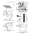
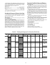
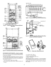
UNIT SIZES 054-074 — To remove shipping brackets, re-
move the 6 screws holding each bracket to the cross rail.
There are 8 brackets per unit. See Fig. 30 or 31.
After removing all shipping brackets, level fan sled using
the adjusting screws. On all 4 corners dimension from cross
rail to fan sled should be as shown in Fig. 30 or 31.
Internal Wiring — Check all electrical connections in
the unit control box; tighten as required.
Refrigerant Service Valves — All units have a
Schrader-type service port on both suction lines. Be sure that
caps on the ports are tight. All units have discharge and suc-
tion service valves on each compressor and a service valve
on each liquid line. Be sure the valves are open before start-
ing unit.
Crankcase Heaters — The crankcase heaters must be
firmly locked into the compressors. The crankcase heaters
are energized when there is power to the unit. Crankcase
heaters must be energized with discharge and suction serv-
ice valves open for at least 24 hours prior to unit start-up in
order to remove liquid refrigerant from the compressor crank-
case and to prevent oil foaming.
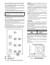
Compressor Oil — Check that compressor oil is vis-
ible in the sight glass of the compressor.All units are factory
charged with oil. See Table 8. Observe oil level closely at
start-up. If oil level is below the sight glass and cannot be
seen, add oil until the level is approximately 1/4 of sight
glass. See Carrier Standard Service Techniques, Refriger-
ants section, for procedures to add or remove oil.
Table 8 — Oil Charge
UNIT SIZE OIL CHARGE (pints)
034 16 ( 8 each circuit)
044 28 (14 each circuit)
054 33 (19 ckt 1, 14 ckt 2)
064 38 (19 each circuit)
074 38 (19 each circuit)
Fig. 30 — Shipping Brackets; 034,044 Units and
50 Series Vertical Discharge 054-074 Units
Fig. 31 — Shipping Brackets; 48Series 054-074 Units
and 50 Series Horizontal Discharge 054-074 Units
38


