


Table 11 — Pressure Switch Settings (psig)
SWITCH CUTOUT CUT-IN
High 426 Ϯ 7 320 Ϯ 20
Low 27 Ϯ 467Ϯ7
Control Circuit, 115 V — This control circuit is pro-
tected against overcurrent by a 5-amp circuit breaker. Breaker
can be reset. If it trips, determine cause of trouble before
resetting.
Control Circuit, 24 V — This control circuit is pro-
tected against overcurrentby a 3.2-amp circuit breaker. Breaker
can be reset. If it trips, determine cause of trouble before
resetting.
Electric Heat (50 Series Units Only)
OVERCURRENT — Heaters are protected by fuses in the
power circuit, located in the heater control box. As with cir-
cuit breakers, determine the cause of fuses tripping before
replacing them. Do not replace with larger fuses. All fuses
are 60 amp.
OVERTEMPERATURE — Heaters are protected by limit
switches mounted in the heater box. They reset automati-
cally once they cool.
Gas Heat (48 Series Units Only)
LIMIT SWITCHES — The maximum supply-air tempera-
ture is controlled by a limit switch located in the gas section.
The limit is designed to trip at 100 F above the maximum
temperature rise shown in Tables 1A and 1B.
When the limit trips, the gas valve is deenergized. Once
the unit cools, the gas valve is reenergized.
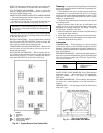
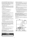
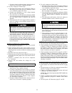
ROLLOUT SWITCH — This switch senses any flame or
excessive heat in the main burner compartment and deen-
ergizes the gas valve. If this occurs, the gas heating system
is locked out until the rollout switch is reset manually. Reset
by pressing the button on the rollout switch. See Fig. 39.
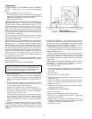
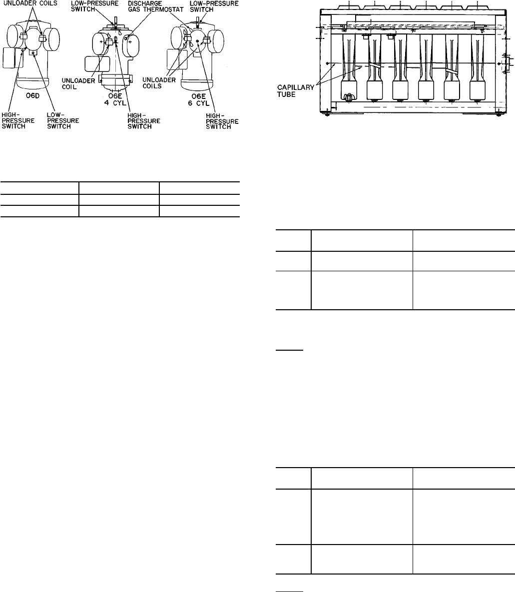
When the rollout switch trips,it likely indicates a flue block-
age. Inspect the unit for any obstruction in the flue system,
for holes on the flue box, or for a defective centrifugal switch
or loose combustion blower. See Fig. 63 for proper location
of the rollout capillary.
TROUBLESHOOTING
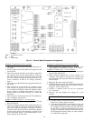
Economizer —
The economizer control consists of an
electronic control board mounted on the back of the cover
plate of the economizer motor with the adjustments and elec-
trical plugs accessible through the top of thecover. The econo-
mizer control is factory wired to the terminals on the motor.
All potentiometers and adjustments are a part of the control
board.
ECONOMIZER MOTOR CHECKOUT — The motor may
be checked out separately from the control board. See
Table 12 for motor checkout. To check out the motor, apply
24 VAC power to terminals T0 and T2 of the control board.
NOTE: The connections to motor terminals T1 and R must
remain in place.
Table 12 — Economizer Motor Checkout
MOTOR
TEST
PROCEDURE EXPECTED RESULT
AND RESPONSE
A Remove wire connected to
terminal W on the motor.
Motor drives open. If not,
replace the motor.
B Remove wire connected to
terminal B on the motor,
leaving W wire discon-
nected (Test A).
Motor drives closed. If not,
replace the motor.
CONTROL BOARD CHECKOUT — To check out the con-
trol board motor, conduct the following 4 tests.
Test 1:
1. Apply 24 VAC power to terminals T0 and T2 of control
board.
2. Remove mixed air sensor connected between terminals
S1 and S2.
3. Remove outdoor-air enthalpy sensor between terminals
ϩϩ and SO.
4. Refer to Table 13.
Table 13 — Economizer Control Board Checkout,
Test 1
MOTOR
TEST
PROCEDURE EXPECTED RESULT
AND RESPONSE
A Turn minimum position
potentiometer fully
counterclockwise.
Motor drives closed. If not,
check minimum position
jumper between
terminals Z and Y, and
check terminal W and T1
connections to motor.
B Turn minimum position
potentiometer fully
clockwise.
Motor drives open. If not,
check terminal B and R
connections to the motor.
Test 2:
1. Apply 24 VAC power to terminals T0 and T2 of the con-
trol board.
2. Apply 24 v between terminals 1 and T2, and jumper ter-
minal T0 to terminal 1.
3. Remove the mixed-air sensor connected between termi-
nals S1 and S2, and replace it with a 5490-ohm resistor.
4. Remove outdoor-air enthalpy sensor between terminals
ϩϩ and SO, and replace it with a 1.2 kOhm resistor.
5. Turn the minimum position potentiometer fully counter-
clockwise.
6. Refer to Table 14.
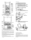
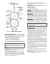
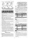
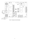
Fig. 62 — Typical Compressor Overtemperature,
High- and Low-Pressure Switch Locations
Fig. 63 — Location of Rollout Switch Capillary Tube
52