


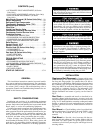
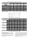
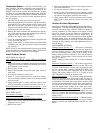
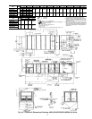
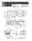
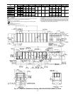
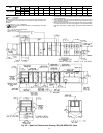

Condensate Drains — See Fig. 4A-4D and Fig. 5 for
drain locations. The drain assemblies, each consisting of a
10-gage plate with a 1
1
⁄
4
-in. half coupling welded to it, are
shipped in the unit fan section. Also included are 16-gage
seal plates to cover the drain holes not being used. Open the
access door marked FAN SECTION to find the drain assem-
blies, seal plates, and 4 screws for each mounting taped to
the unit basepan.
After the unit has been set in place on the roof:
1. Select the appropriate drain locations. The 034 units have
6 drain holes (3 per side), and the 044-074 units have 8
drain holes (4 per side). Two holes on each side must be
selected for condensate drains as shown in Fig. 5, and the
remaining holes must be sealed.
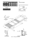
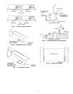
2. Remove the drain assemblies and attach them to the bot-
tom of the unit base rails at the preferred drain locations
using the screws provided. See Fig. 6.
NOTE: Use a trap at least 4-in. deep.
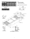
3. Cover the remaining drain holes with the seal plates and
screws provided. See Fig. 7.
4. Apply a bead of RTV or similar sealant around the drain
assemblies and seal plates where they attach to the base
rail. See Fig. 8.
NOTE: If unit is slab mounted, holes will need to be drilled
in the side of the base rail and the holes factory-drilled in the
bottom of the base rail will need to be plugged.
Install Outdoor Hoods
UNIT SIZES 034 AND 044
25% Outdoor-Air Hoods (Units Without Economizer
Option)
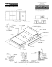
1. Outdoor-air hoods are shipped bolted to the unit in a ship-
ping position. Remove the 6 screws holding each 25% air
hood shipping cover in place.
2. Replace the 6 screws.
3. Remove the holddown screw from each upper corner of
each hood.
4. Pivot hoods outward (2 hoods total).
5. Install 17 screws around outside of each hood. (Screws
are in the fastener package taped to the basepan inside
the fan section.)
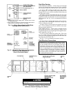
6. Apply a bead of RTV or similar sealant to corner of each
hood at pivot point to prevent water leaks. See Fig. 9.
Economizer Hoods (Units With Economizer Option) —Fol-
low the same procedure described in 25% Outdoor-Air Hoods
section above.
UNIT SIZES 054-074
25% Outdoor-Air Hoods — The outdoor-air hoods are fac-
tory installed on the 054-074 units.
Economizer Hoods (Units With Economizer Option)
1. Remove the 6 screws holding each of the 4 economizer
shipping covers in place.
2. Replace the screws.
3. Remove the holddown screw from each upper corner of
each economizer hood.
4. Pivot hoods outward. (There is a total of 4 hoods.)
5. Install 18 screws, (5 each side, 6 top, and 2 bottom), around
the outside of each hood. (Screws are in the fastener pack-
age taped to the basepan inside the fan section.)
6. Apply a bead of RTV or similar sealant to corner of econo-
mizer hood at pivot point to prevent water leaks. (See
Fig. 9.)
Outdoor-Air Inlet Adjustments
MANUALOUTDOOR-AIR DAMPER (UnitsWithout Econo-
mizer Option) —Allunits exceptthose equipped with afactory-
installed economizer have a manual outdoor-air damper to
provide ventilation air. This damper can be preset to admit
up to 25% outdoor air into the return-air compartment. To
adjust, loosen the blade limiter screws as shown in Fig. 10
and move the damper to the desired position. Then retighten
the blade limiter screws to secure the damper. See Fig. 10.
(To make this adjustment, it isnecessary to remove the screens
covering the hood opening and make adjustments from in-
side the hood.)
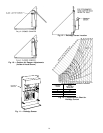
ECONOMIZER SETTINGS
Enthalpy Sensor (See Fig. 11.) — This sensor is located be-
hind the filters in the end economizer hood (the upper hood
on sizes 054-074). See Fig. 12. For maximum benefit of out-
door air, set enthalpy sensor control to the A setting. At this
setting, when the relative humidity is 50%, and the outdoor
air is below 74 F, the sensor’s relay contacts will be closed.
See Fig. 13 and 14.
NOTE: Enthalpy control setting dial is on the economizer
motor.
Mixed-Air Thermistor (MAT) — This control set point ad-
justment is on the top of the economizer motor. This motor
is located in the return-air section, and is accessed by open-
ing the access panel marked FILTER SECTION. See
Fig. 15. Set MAT set point adjustment dial to the desired
setting. The factory setting is 55F±5°F;range is 40 to
90 F. The MAT is located on the filter rack.
Damper Vent Position — The position setting adjustment is
located on the cover of the economizer motor. See Fig. 15.
Adjust by setting the fan switch at ON position (continuous
fan operation), and setting the system selector switch to OFF
position. Then turn adjustment screw slowly until the damp-
ers assume the desired vent position. Do not manually op-
erate the damper motor; damage to the motor may result.
Economizer Damper Linkage Adjustment — When replac-
ing economizer damper motors, or if the linkage has come
loose, it is critical that the linkages be adjusted correctly.
They are sensitive, and incorrect adjustment can cause the
motor to stall.
NB,NPUnit Minimum PositionSet Point — Minimumecono-
mizer position is set using the keypad and display module.
Refer to Control and Troubleshooting literature for more
details.
10