


Initial Check
IMPORTANT: Do not attempt to start unit, even mo-
mentarily, until all items on the Start-Up Checklist and
the following steps have been completed.
1. Verify unit has been installed per the Installation section
of this literature.
2. Certify that all auxiliary components (sensors, controls,
etc.) have been installed and wired to the control boxes
per these instructions, the Controls and Troubleshooting
literature (DK,DY,NB,NP units only), and the unit wiring
label diagrams.
3. Verify that pressure hoses (static, duct, etc.) are properly
attached, routed, and free from pinches or crimps that may
affect proper control operation.
4. Set any control configurations that are required (field-
installed accessories, etc.). The unit is factory configured
for all appropriate factory-installed options with the ap-
plicable controls programmed to the default values. See
unit Controls and Troubleshooting literature for appli-
cable configuration values.
5. Enter unit set points (if applicable). The unit is shipped
with the set point default values shown in the Controls
and Troubleshooting literature (as applicable). If a dif-
ferent set point is required, change per the example shown
under Set Point Function section in appropriate unit Con-
trols and Troubleshooting literature.
6. Configure schedule subfunctions (if applicable): occu-
pied, unoccupied, and holiday periods. See Schedule Func-
tion section in Controls and Troubleshooting literature for
details on setting periods.
7. Verify that control time periods programmed meet cur-
rent requirements.
8. Check all electrical connections to be sure they are tight.
START-UP
General
1. Put the ON/OFF switch in the ON position. Close the con-
trol circuit breaker (CCB), which will energize the con-
trol circuit and the crankcase heaters.
2. For PIC and VAV units, refer to Controls and Trouble-
shooting literature for quick test details.
3. Complete Pre-Start-Up section items and Start-Up Check-
list.
Operating Sequences — Base unit operating se-
quences arepresented below. Refer tounit Controls andTrouble-
shooting literature for details on VAV and PIC controls op-
eration.
COOLING, UNITS WITHOUT ECONOMIZER — Unit
power on, system selector switch set at COOL or AUTO.
position, fan switch set at AUTO. position.
On a call for cooling, Y1 on the thermostat subbase closes,
energizing compressor no. 1 as first stage of cooling. (Com-
pressor no. 1 is always the larger of the 2 unit compressors.)
If cooling load cannot be satisfied with only first-stage cool-
ing, Y2 on the thermostat will close, energizing compressor
no. 2.
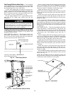
Condenser fans are energized with compressor no. 1. The
no. 1 fan runs continuously while the unit is on mechanical
cooling; the no. 2 fan is cycled on and off in response to
outdoor ambient temperature for head pressure control. Check
cooling effects at a setting below room temperature. Reset
thermostat at a setting above room temperature. Compres-
sors will shut off.
HEATING, UNITS WITHOUT ECONOMIZER
48 Series Low-Heat Units — Unit power on, thermostat sys-
tem switch set at HEAT or AUTO. position, and fan switch
set at AUTO. position.
First-stage thermostat (W1) calls for heat. Time-delay re-
lay (built into constant volume control board), controlling
evaporator fan, begins timer sequence (55 ± 10-second de-
lay). Induced-draft contactor closes and induced-draft motor
starts.
Centrifugal switch closes. Pilot valve opens, allowing gas
to flow to first-stage pilot. Spark ignitor ignites pilot flame.
Sensor detects flame, energizes main gas valve coil and main
gas valve opens. Gas flows to main burners and first-stage
burners ignite. Spark ignitor shuts off and pilot remains on.
The spark ignitor will continue to spark for 90 seconds
until pilot flame is sensed. If the pilot fails to ignite or the
sensor fails to detect flame, the pilot valve closes and the
spark ignitor shuts off for 300 seconds (5 minutes). During
this time the induced draft motor remains on to purge any
unburnt gas from the combustion tubes. This ignition se-
quence will repeat indefinitely.
When time-delay sequence is complete, time-delay relay
closes and evaporator-fan motor starts.
When additional heat is needed on 034,044 units, W2 is
energized and a second coil in the main gas valve is ener-
gized. Thisbrings on an additional stage ofheat. When second-
stage thermostat is satisfied, the second-stage gas valve coil
is deenergized.
When additional heat is needed on 054-074 units, W2 is
energized,and pilot valve number2 opens. Gasflows to second-
stage pilot, and spark ignitor ignites pilot flame. Sensor de-
tects flame, energizes the main gas valve coil, and main gas
valve number 2 opens. Gas flows to main burners and second-
stage burners ignite.Second-stage spark ignitor shuts off. When
second-stage thermostat is satisfied, thesecond-stage gas valve
coil is deenergized.
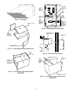
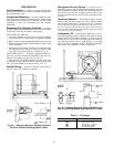
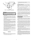
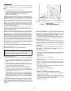
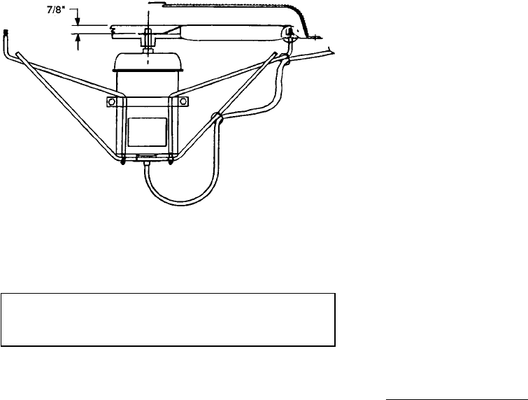
Fig. 32 — Condenser-Fan Adjustment
41