


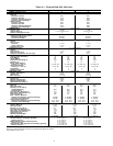
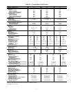
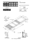
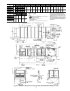
UNIT SIZE
WEIGHT A B C D E F G H J
lb kg mm ft-in. mm ft-in. mm ft-in. mm ft-in. mm ft-in. mm ft-in. mm ft-in. mm ft-in. mm ft-in.
48DJD,DKD,NPD
034
5641 2559 4498 14-9
1
⁄
8
3662 12-0
3
⁄
16
7278 23-10
9
⁄
16
1709 5-7
5
⁄
16
2216 7- 3
1
⁄
4
4228 13-10
7
⁄
16
2746 9-0
1
⁄
8
— — 3626 12-10
9
⁄
16
48DJE,NPE 5770 2617 4474 14-8
1
⁄
8
50DW,DY,NB 5970 2708 4044 13-3
1
⁄
4
48DJD,DKD,NPD
044
6541 2967 5255 17-2
7
⁄
8
4497 14-9
1
⁄
16
8496 27-10
1
⁄
2
2328 7-7
5
⁄
8
2091 6-10
5
⁄
16
4706 15-5 3363 11-0
3
⁄
8
3769 12-4
3
⁄
8
4762 15-7
1
⁄
2
48DJE,NPE 6670 2708 5229 17-1
7
⁄
8
50DW,DY,NB 6620 3003 4823 15-9
7
⁄
8
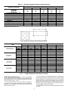
UNIT SIZE
KL
mm ft-in. mm ft-in.
48DJD,DKD,NPD
034 4741 15-6 6797 22-3
5
⁄
8
48DJE,NPE
50DW,DY,NB
48DJD,DKD,NPD
044 5576 8-3
1
⁄
2
8015 26-3
9
⁄
16
48DJE,NPE
50DW,DY,NB
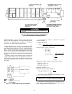
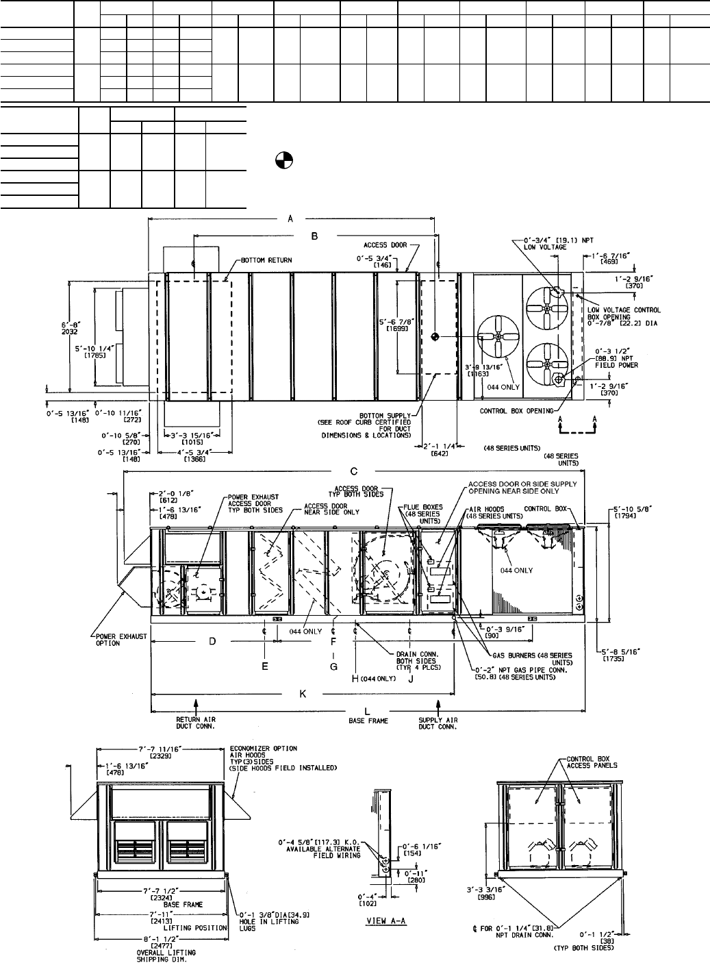
LEGEND
CONN — Connection
DIM — Dimension
NOTES:
1. Dimensions in [ ] are in millimeters.
2. CenterofGravityincludeseconomizer.Unitweightdoes
not include economizer.
3. Unit clearances:
Top — Do not restrict condenser fans
Control Box End — 6Ј-0Љ
Sides — 6Ј-0Љ
EconomizerEnd—6Ј-0Љ(exceptpowerexhaustunits10Ј-0Љ)
Forsmallerserviceandoperationalclearances,con-
tact Carrier Product Engineering Department.
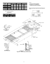
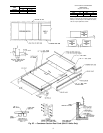
4. Vertical dischargeductsdesigned tobeattached to
accessoryroofcurb. Ifunitismountedondunnage,
supporttheductsusingcrossbracesasdoneonthe
accessory roof curb.
5. When unit is slab mounted, locate the condensate
drainaslowas possibleonverticalfaceofbaserail
atthesamelocationasthestandardcondensatedrain
(usingfactorysuppliedfitting).Plugfactorydrilledcon-
densate hole.
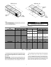
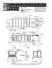
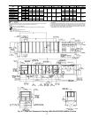
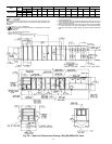
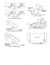
Fig. 4A — Base Unit Dimensional Drawing; 48DJ,DK,NP/50DW,DY,NB034,044 Units
11