


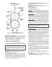
Moisture/Liquid Indicator — A clear flow of liquid
refrigerant indicates sufficient charge in the system. Bubbles
indicate undercharged system or the presence of noncon-
densables. Moisture in the system measured in parts per mil-
lion (ppm) changes the color of the indicator:
Green — moisture below 45 ppm (dry)
Chartreuse — 45 to 130 ppm (caution!)
Yellow — moisture above 130 ppm (wet)
Change filter driers at the first sign of moisture in the sys-
tem. See Carrier Charging Handbook for more information.
IMPORTANT: Unit must be in operation at least
12 hours before moisture indicator can give an accu-
rate reading. With unit running, indicating element must
be in contact with liquid refrigerant to give a true
reading.
Filter Drier — Replace whenever the moisture/liquid in-
dicator shows moisture in the system.
Liquid Line Service Valve — Located immediately
ahead of the filter drier, this valve has a 1/4-in. flare con-
nection for field charging. With the liquid circuit shut, the
compressor can be used to pump the refrigerant down into
the high side. The refrigerant can then be stored there by
closing the compressor discharge valve.
Compressor Discharge Service Valve — Each
compressor has one.
Compressor Suction Service Valve — Each com-
pressor has one.
Protective Devices
COMPRESSOR PROTECTION
Overcurrent — Each compressor has one manual reset, cali-
brated trip, magnetic circuit breaker. Do not bypass connec-
tions or increasethe size of thecircuit breaker to correct trouble.
Determine the cause and correct it before resettingthe breaker.
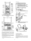
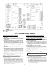
Overtemperature — Each 06D compressor has an internal
protector to protect it against excessively high discharge gas
temperatures. Each 06E compressor has an external dis-
charge gas thermostat. See Fig. 62. They will reset, but the
circuit will automatically be locked out by the control board.
Unit must be manually reset by interrupting control power.
Crankcase Heater — Each compressor has a crankcase heater
to prevent absorption of liquid refrigerant by oil in the crank-
case when the compressor is idle. Since 115-v power for the
crankcase heaters is drawn from the unit control circuit, main
unit power must be on for the heaters to be energized.
IMPORTANT: After a prolonged shutdown or service
job, energize the crankcase heaters for 24 hours before
starting the compressor.
Compressor Lockout — If any of the safeties (compressor
internal thermostat [06D compressors only], high-pressure,
or low-pressure) trip, or if there is a loss of power to the
compressors, the compressors will be locked out. To reset
DJ,DW units, manually move the thermostat setting. To re-
set DK,DY,NB,NP units, consult the controls and trouble-
shooting literature for the appropriate unit for details.
EVAPORATOR-FAN MOTOR PROTECTION —Amanual
reset, calibrated trip, magnetic circuit breaker protects against
overcurrent. Do not bypass connections or increase the size
of the breaker to correct trouble. Determine the cause and
correct it before resetting the breaker.
CONDENSER-FAN MOTOR PROTECTION — Each
condenser-fan motor is internally protected against over-
temperature. They are also protected against a severe over-
current condition by manual reset, calibrated trip, magnetic
circuit breakers on acommon circuit.As with the circuit break-
ers, do not bypass connections or increase breaker size to
correct trouble. Determine the cause and correct it before
resetting the breaker.
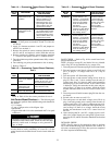
HIGH-AND LOW-PRESSURE SWITCHES — See Fig. 62
for compressor mounting locations. Settings forthese switches
are shown in Table 11. If either switch trips, that refrigerant
circuit will be automatically locked out by the controls. To
reset, interrupt control power.
NOTE: When a pressure transducer is used, the low pres-
sure trip point is the same as the low-pressure switch.
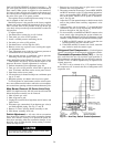
Relief Devices — All units have relief devices to pro-
tect against damage from excessive pressures (i.e., fire).These
devices protect the high and low side.
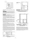
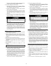
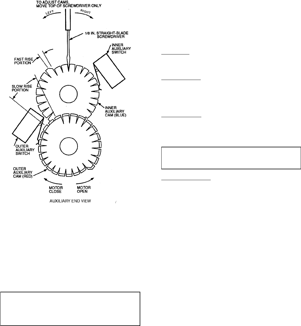
Fig. 61 — Auxiliary Switch Adjustment
51