


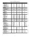
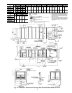
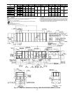
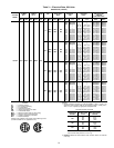
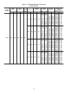
UNIT SIZE
WEIGHT A B C D E F G
lb kg mm ft-in. mm ft-in. mm ft-in. mm ft-in. mm ft-in. mm ft-in. mm ft-in.
48DJD,DKD,NPD
054
8700 3946
5969 19-7 6717 22-0
7
⁄
16
1163 3-9
13
⁄
16
11,524 37-9
11
⁄
16
2718 8-11 6541 21-5
1
⁄
2
11,140 36-6
9
⁄
16
48DJE,NPE 8820 4000
50DW,DY,NB 8250 3742 6045 19-10 7676 25-2
3
⁄
16
2830 9-3
3
⁄
4
6427 21-1
48DJD,DKD,NPD
064
9000 4082
5969 19-7 6717 22-0
7
⁄
16
1163 3-9
13
⁄
16
11,524 37-9
11
⁄
16
2718 8-11 6541 21-5
1
⁄
2
11,140 36-6
9
⁄
16
48DJE,NPE 9120 4137
50DW,DY,NB 8550 3878 6045 19-10 7676 25-2
3
⁄
16
2830 9-3
3
⁄
4
6427 21-1
48DJD,DKD,NPD
074
9420 4273
6401 21-0 6717 22-0
7
⁄
16
1163 3-9
13
⁄
16
12,433 40-9
1
⁄
2
3543 11-7
1
⁄
2
5715 18-9
12,049 39-6
3
⁄
8
48DJE,NPE 9550 4332
50DW,DY,NB 8970 4069 6477 21-3 7676 25-2
3
⁄
16
3694 12-1
3
⁄
4
5563 18-3
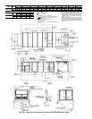
LEGEND
CONN — Connection
DIM — Dimension
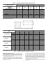
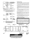
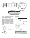
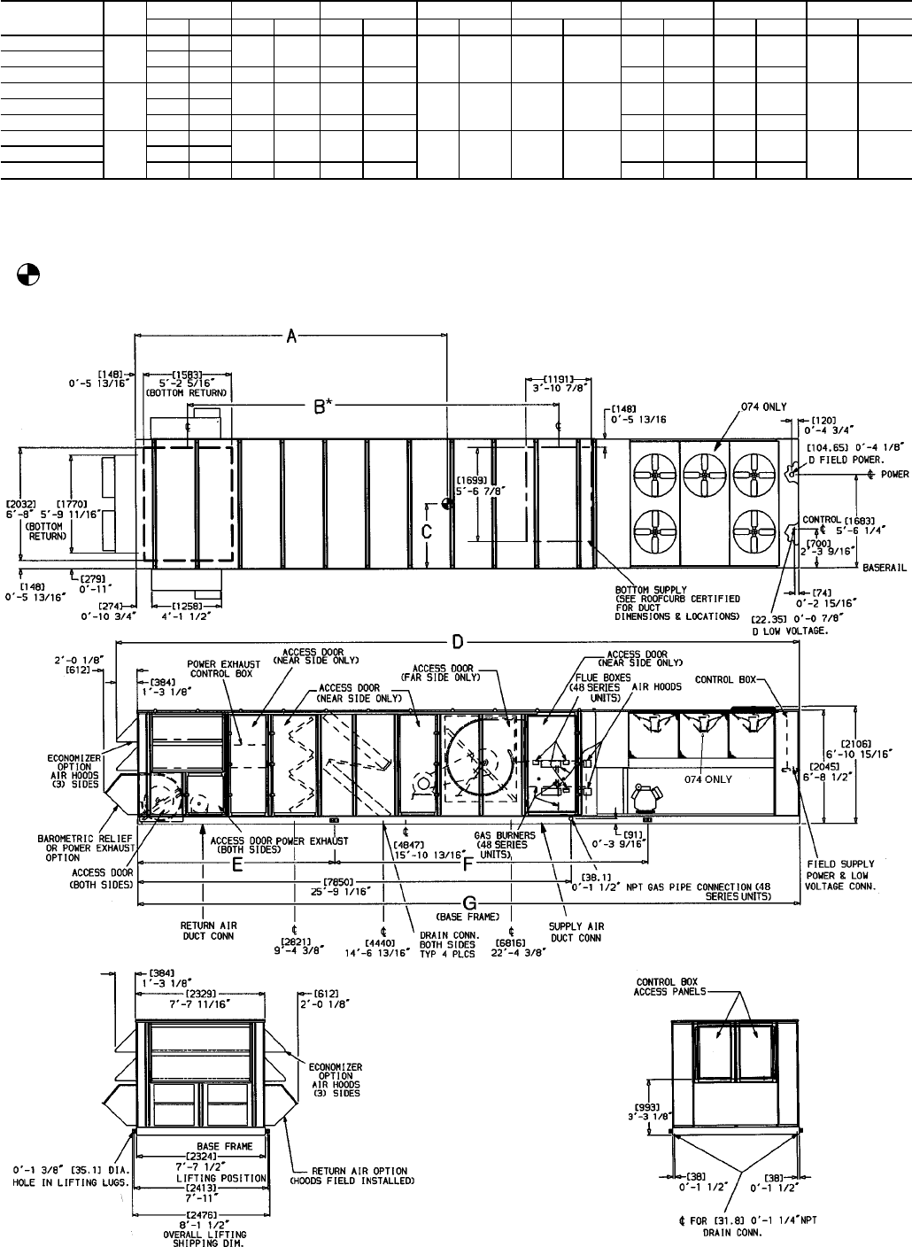
*Dimensionshown isfor 48series units.On 50seriesunits, dimensiongiven ismeasured from
economizer end of unit to drainconnection closest to condenser fans.
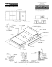
NOTES:
1. Dimensions in [ ] are in millimeters.
2. Center of Gravity includes economizer. Unit weight does not include economizer.
3. Unit clearances:
Top — Do not restrict condenser fans
Control Box End — 6Ј-0Љ
Sides — 6Ј-0Љ (except power exhaustunits 10Ј-0Љ)
Economizer End — 6Ј-0Љ (except powerexhaust units 10Ј-0Љ)
For smaller service and operational clearances, contact Carrier Product Engineering
Department.
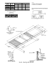
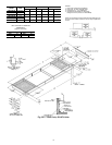
4. Verticaldischargeductsdesignedtobeattachedtoaccessoryroofcurb.Ifunitismounted
on dunnage,support theducts usingcross braces asdone onthe accessoryroof curb.
5. When unit isslab mounted, locate the condensate drain as low aspossible on vertical
face of base rail at the same location as the standard condensate drain (using factory
supplied fitting). Plug factory drilled condensatehole.
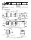
Fig. 4C — Base Unit Dimensional Drawing; 48DJ,DK,NP/50DW,DY,NB054-074 Units
13