


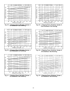
LIQUID SERVICEVALVES, FILTER DRIERS,AND SIGHT
GLASSES
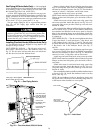
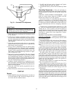
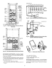
Sizes 034 and 044 —Accessto these components is through
the access panel on the right side of the unit. See Fig. 34.
There is also a Schrader port in each suction line that is ac-
cessible through this same panel. When charging unit, route
service line through the round holes and replacepanel to mini-
mize air bypass.
Sizes 054-074 — Access to these components is from the
side of the unit as shown in Fig. 34.
EVAPORATOR-FAN MOTORS, PULLEYS, AND BELTS
— Access to these components is through the 2 doors la-
beled FAN SECTION on each side of the unit.
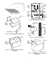
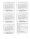
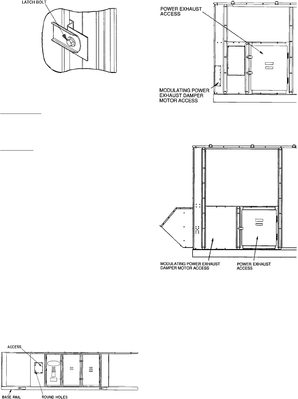
POWER EXHAUST MOTORS, PULLEYS, AND BELTS
— Access to these components is through the door below
the side economizer hoods on either side of the unit. See
Fig. 35 and 36.
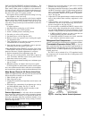
UNITCONTROL BOX—Access tothis component isthrough
the doors marked ELECTRICAL SECTION on the con-
denser end of the unit (when facing the condenser coil).
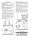
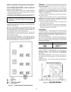
GAS HEAT SECTION (48 Series Units Only) — Access to
the gas heat section is through the door labeled HEAT SEC-
TION on the left side of the unit (when facing condenser
end). See Fig. 37 and 38.
All gas system components are in the gas section.
MAIN AND PILOT BURNERS (48 Series Units Only) —
At the beginning of each heating season, inspect for dete-
rioration due to corrosion or other causes. Observe the pilot
and main burner flames and adjust if necessary. See Auto-
matic Pilot Adjustment or Main Burners Adjustment Section
on pages 49 and 50.
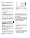
FLUE GAS PASSAGEWAYS (48 Series Units Only) — The
flue collector box and heat exchanger cells may be inspected
by removing the combustion air blower(s), flue box cover,
and main burner assembly. See Fig. 39 and 40. If cleaning
is required, remove heat exchanger baffles through the flue
box and clean all parts with a wire brush. When replacing
heat exchanger baffles, be sureto replace screw through clamp
on baffle retaining rod into the vestibule plate.
COMBUSTION AIR BLOWER (48 Series Units Only) —
Clean periodically to assure proper airflow and heating ef-
ficiency. Inspect blower wheel every fall and periodically dur-
ing the heating season. For first heating season,inspect blower
wheel bimonthly to determine proper cleaning frequency. If
cleaning is required, remove blower assembly from unit and
then disassemble and clean. See Fig. 41.
Fig. 35 — Modulating Power Exhaust Damper
Motor Access, 034 and 044 Units
Fig. 36 — Modulating Power Exhaust Motor
Access, 054-074 Units
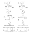
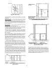
Fig. 33 — Door Latch
Fig. 34 — Typical Filter Drier and Liquid Service
Valve Access
43