


54
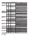
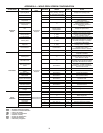
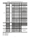
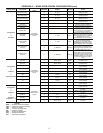
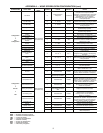
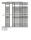
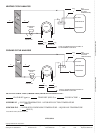
APPENDIX A — WSHP SCREEN OPEN CONFIGURATION (cont)
LEGEND
SCREEN NAME POINT NAME
PASSWORD
LEVEL
EDITABLE RANGE DEFAULT NOTES
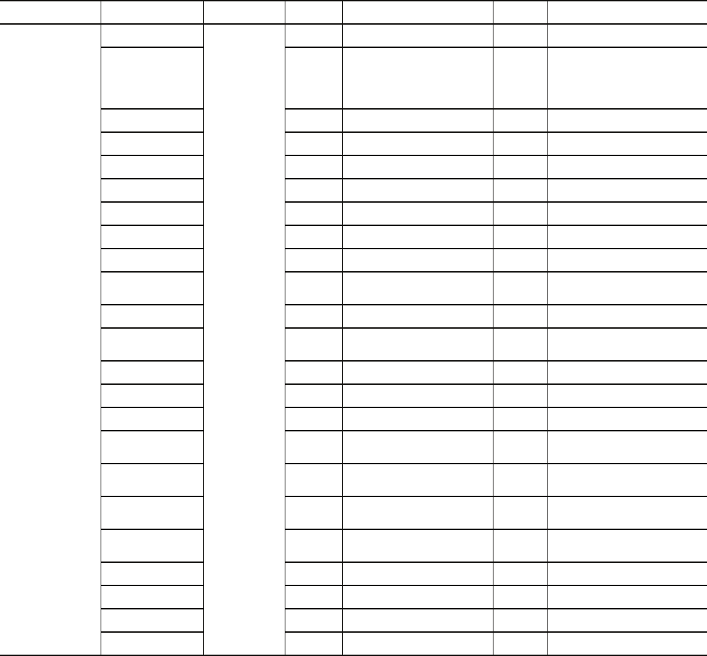
Configuration
Service
Configuration
# of Fan Speeds
Admin Password
level access only
X 1,2,3 3
Used to set number of
fan motor speeds
G Output Type X Fan On/Fan Low Fan On
When set to Fan On, G output is
energized when ever any fan speed
is active (required for ECM and Fan
control board). When set to Fan
Low, output is only energized for
Low Speed
Compressor Stages X One Stage/Two Stages One Stage
Defines the number of
stages of compression
Reversing Valve Type X O type output/B type output O type
Determines reversing valve
signal output type
Leaving Air Auxiliary
Heat Type
X
None/2-Position HW/1 Stage
Electric/Modulating HW
None
Determines Auxiliary
Reheat Coil Type
Entering Air Water
Economizer Type
X None/2-Position/Modulating None
Determines Entering Air
Economizer Coil Type
2-Position Water
Valve Type
X Normally Closed/Normally Open
Normally
Closed
Determines type of 2-position
water valve used
Modulating Water
Valve Type
X Normally Closed/Normally Open
Normally
Closed
Determines type of modulating
water valve used
Ventilation Damper
Type
X None/2-Position/DCV None
Determines Type of ventilation
damper control to be used
Damper Actuator Type X (0-10 volt)/(2-10 volt) 0-10 volt
Used to determine ventilation
damper output signal range
(closed - open)
Humidity Sensor X None/Installed None
Set to Installed if Humidity
sensor is present
Factory Dehumidifica-
tion Reheat Coil
X None/Installed None
Set to Installed if factory-installed
dehumidification reheat coil
is present
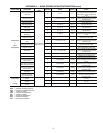
Occupancy
Input Logic
X Occupied Open/Occupied Closed
Occupied
CLOSED
Used to determine external occu-
pancy switch contact occupied state
Condensate Switch
Alarm Delay
X 5 - 600 seconds 10 sec
Delay before equipment alarms on
high condensate level
Condensate Switch
Alarm State
X Alarm OPEN/Alarm CLOSED
Alarm
CLOSED
Determine Alarm state of
condensate switch input
Minimum Condenser
Water Temperature in
Heating
X25 - 60 F60 F
Determines the minimum
acceptable water loop temperature
to start heating
Maximum Condenser
Water Temperature in
Heating
X 65 - 100 F 90 F
Determines the maximum
acceptable water loop temperature
to start heating
Minimum Condenser
Water Temperature in
Cooling
X30 - 60 F60 F
Determines the minimum
acceptable water loop temperature
to start cooling
Maximum Condenser
Water Temperature in
Cooling
X 85 - 120 F 95 F
Determines the maximum
acceptable water loop temperature
to start cooling
IAQ sensor
minimum input
X 0 - 5 ma 4 ma
Minimum output current (mA)
for IAQ sensor
IAQ sensor
maximum input
X 5 - 20 ma 20 ma
Maximum output current (mA) for
IAQ sensor
IAQ sensor
minimum output
X 0 - 9999 ppm 0 ppm
Corresponding value in ppm for
minimum output current
IAQ sensor
maximum output
X 0 - 9999 ppm 2000 ppm
Corresponding value in ppm for
maximum output current
→
°°
°°
°°
°°
BAS — Building Automation System
DCV — Demand Controlled Ventilation
IAQ — Indoor Air Quality
OAT — Outdoor Air Temperature
RH — Relative Humidity
SAT — Supply Air Temperature
SPT — Space Temperature
TPI — Third Party Integration