


31
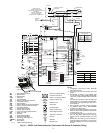
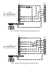
OPTIONAL WALL-MOUNTED THERMOSTAT — The
50PEC water source heat pump units are built with standard in-
ternal thermostats in either manual changeover (MCO) or auto-
matic changeover (ACO) configuration. Refer to Fig. 17-20.
When desired, the unit can be furnished with a 24-v control
circuit which is field wired to a Carrier-supplied accessory re-
mote thermostat. Most heat pump thermostats can be used with
the controller. Use a thermostat with Y, G, O and W outputs.
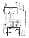
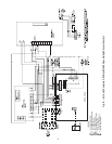
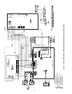
Refer to unit wiring diagrams in Fig. 21 and 22 and Aquazone
Controls, Operation, and Troubleshooting Instructions for addi-
tional information.
Vendor installation instructions and additional installation
information is shipped with each thermostat.
NOTE: Low-voltage wiring between the unit and the wall ther-
mostat must comply with all applicable electrical codes
(i.e., NEC and local codes), and be completed before the unit is
installed.
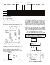
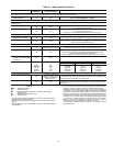
Table 3 lists recommended wire sizes and lengths to install
the thermostat. The total resistance of low-voltage wiring must
not exceed 1 ohm. Any resistance in excess of 1 ohm may
cause the control to malfunction because of high voltage drop.
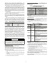
Table 3 — Recommended Thermostat Wire Sizes
*Length = Physical distance from thermostat to unit.
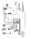
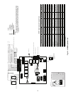
OPTIONAL PREMIERLINK™ CONTROLLER — This di-
rect digital controller (DDC) allows the water source heat
pump to be incorporated into a Carrier Comfort Network
®
(CCN) system installation. PremierLink control is factory-
installed with the Complete C controller, or field-installed with
the Deluxe D control option. Refer to Fig. 23 and 24.
WSHP OPEN WIRING — The WSHP Open controller will
be factory wired to the Complete C or Deluxe D control board,
however, the system wiring will need to be completed utilizing
WSHP Open controller wiring diagrams and the Third Party
Integration (TPI) Guide. Factory installation includes harness,
LWT (leaving water temperature), supply air, and condensate
sensor.
Wiring Sensors to Inputs
— Sensors can be wired to the
WSHP Open controller’s inputs. See Table 4.
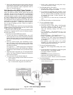
All field control wiring that connects to the WSHP Open con-
troller must be routed through the raceway built into the corner
post. The raceway provides the UL required clearance between
high and low-voltage wiring.
1. Pass control wires through the hole provided in the corner
post.
2. Feed the wires through the raceway to the WSHP Open
controller.
3. Connect the wires to the removable Phoenix connectors.
4. Reconnect the connectors to the board.
Field-Supplied Sensor Hardware
— The WSHP Open con-
troller is configurable with the following field-supplied sen-
sors. See Table 4.
Table 4 — Field-Supplied Sensors for
WSHP Open Controller
NOTE: BACview
6
Handheld or Virtual BACview can be used as the
user interface.
For specific details about sensors, refer to the literature sup-
plied with the sensor.
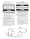
Wiring a SPT Sensor
— A WSHP Open controller is connect-
ed to a wall-mounted space temperature (SPT) sensor to moni-
tor room temperature using a Molex plug.
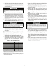
The WSHP Open system offers the following SPT sensors.
See Table 5.
Table 5 — SPT Sensors
*The SPT Pro Plus fan speed adjustment has no effect in this
application.
Wire SPT sensors to the WSHP Open controller’s Rnet port.
An Rnetbus can consist of any of the following combinations
of devices wired in a daisy-chain configuration:
• 1 SPT Plus, SPT Pro, or SPT Pro Plus sensor
• 1 to 4 SPT Standard sensors
• 1 to 4 SPT Standard sensors and 1 SPT Plus, SPT Pro, or
SPT Pro Plus sensor
• Any of the above combinations, plus up to 2 BACview
6
Handheld but no more than 6 total devices
NOTE: If the Rnetbus has multiple SPT Standard sensors, each
sensor must be given a unique address on the Rnetbus. See the
Carrier Open Sensor Installation Guide.
Use the specified type of wire and cable for maximum signal
integrity. See Table 6.
WIRE SIZE MAX WIRE LENGTH*
18-Gage 75 ft
16-Gage 125 ft
14-Gage 200 ft
WARNING
Disconnect all power to the unit before performing mainte-
nance or service. Unit may automatically start if power is
not disconnected. Failure to follow this warning could
cause personal injury, death, and/or equipment damage.
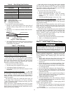
SENSOR NOTES
Space Temperature Sensor
(SPT)
Field Installed (Must be used with
WSHP Open controller.)
Outdoor Air
Temperature Sensor
Network Sensor
Indoor Air Quality Sensor
(Separate Sensor)
Required only for demand
control ventilation.
Space Relative Humidity
Sensor
Separate Sensor
SENSOR
PART
NUMBER
FEATURES
SPT
Standard
SPS
• Local access port
• No operator control
SPT Plus SPPL
• Slide potentiometer to adjust set point
• Manual on button to override schedule
• LED to show occupied status
• Local access port
SPT Pro SPP
•LCD display
• Manual on button to override schedule
• Warmer and cooler buttons to adjust set
point
• Info button to cycle through zone and
outside air temperatures, set points, and
local override time
• Local access port
SPT Pro
Plus
SPPF
• LCD display
• Manual on button to override schedule
• Warmer and cooler buttons to adjust set
point
• Info button to cycle through zone and
outside air temperatures, set points, and
local override time
• Local access port
• Fan speed*