


29
012207-1BT485BT
LED1
DB
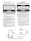
Install BT485 where device is
located at the end of network
segment only.
+ 24vac
(If not installed, it must be connected to DO-5)
DEHUMIDIFY OUTPUT CONTACT (DO-6) (FACTORY OPTION)
FAN SPEED (DO-7) (MED OR LOW)
OA DAMPER (AO-2)
FAN SPEED (DO-8) (HIGH OR FAN ON )
LWT (Input 6)
SAT (LAT) (Input 7)
SPACE CO2
SENSOR
+24vac
4-20mA
+
-
RED
YLW
ORN
BRN
PINK
VIO
PINK
AO1 – Aux Reheat or Cond.
WTR. Loop Econ. (AO 1)
BLU
RED
BRN
-Gnd
Condensate
Overflow Switch
(DI-3/Dry Contact)
GRN
Fan (DO-1) (Fan On or Low Speed)
PINK
Aux Heat (DO-2)
ORN
Reversing Valve (DO-3)
Comp #2 (DO-4)
Comp #1 (DO-5)
BLU
Comp Status (DI-5)
SPT PLUS Sensor
Shown
+12V
Rnet-
Rnet+
Gnd
RED
BLACK
WHITE
GREEN
To WSHP Controller
Rnet Terminals (J13)
FIELD INSTALLED
123 4
0
5
1
6
2
7
3
8
4
9
0
5
1
6
2
7
3
8
4
9
12
3 45
6
7 8
O
N
1
2 3
4
5
67
8
12
1
2
3
4
123 4
1
2 3
123 45678
GREEN
WHITE
BLACK
RED
Field Installed
J5
J12
J13
J20
J19
J22
J17
J11
J14
To
SPT PLUS
1
2
3
45
6
11
10
7
J4
J1 J2
SW3
MSB
LSB
MSTP Baud
9600 19.2k 38.4k 76.8k
SPACE RH
SENSOR
+24vac
4-20mA
+
-
WHT
FIELD INSTALLED (OPTIONAL) – SEE NOTE 2
Local Access Port
a50-8380
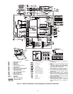
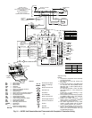
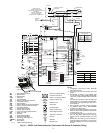
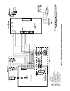
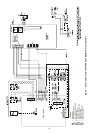
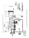
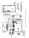
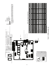
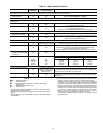
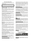
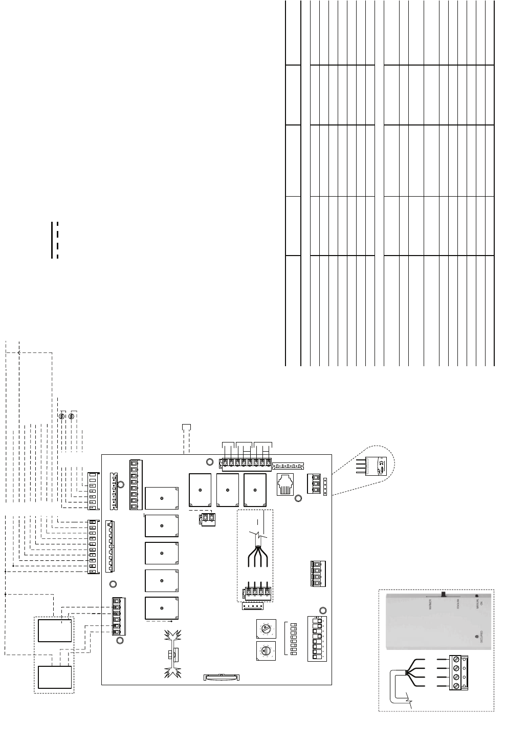
Fig. 29 — WSHP Open Control
WSHP Open Inputs and Outputs Table
*These inputs are configurable.
INPUT/OUTPUT TYPE PART NUMBERS TYPE OF I/O
CONNECTION
PIN NUMBERS
CHANNEL
DESIGNATION
Inputs
Space Temperature Sensor SPS, SPPL, SPP Communicating J13, 1 - 4 Local Access Port
Space Relative Humidity 33ZCSENSRH-01 AI (4 - 20mA) J4, 5 and 6 Analog Input 1
Indoor Air Quality 33ZCSENCO2 AI (4 -20mA) J4, 2 and 3 Analog Input 2
Condensate Switch N/A BI (Dry Contacts) J1, 2 Binary Input 3
Stage 1 Compressor Status N/A BI (Dry Contacts) J1, 10 Binary Input 5
Leaving Condenser Water Temperature 10K Type II AI (10K Thermistor) J2, 1 and 2 Analog Input 6
Supply Air Temperature 33ZCSENSAT AI (10K Thermistor) J2, 3 and 4 Analog Input 7
Outputs
Modulating Valve (Auxiliary Heat/Water
Economizer)
N/A AO (0-10Vdc/2 - 10Vdc) J2 4 and 5* Analog Output 1
Outside Air Damper N/A AO (0-10Vdc/2 - 10Vdc) J22 1 and 2* Analog Output 2
Supply Fan On/Low Speed
(3 Speed Only)
N/A BO Relay (24VAC, 1A) J1, 4* Binary Output 1 (G)
Auxiliary Heat or 2-Position Water Loop
Economizer
N/A BO Relay (24VAC, 1A) J1, 5* Binary Output 2
Reversing Valve (B or O Operation) N/A BO Relay (24VAC, 1A) J1, 6* Binary Output 3 (RV)
Compressor 2nd Stage N/A BO Relay (24VAC, 1A) J1, 7 Binary Output 4 (Y2)
Compressor 1st Stage N/A BO Relay (24VAC, 1A) J1, 8 Binary Output 5 (Y1)
Dehumidification Relay N/A BO Relay (24VAC, 1A) J11, 7 and 8 (NO) Binary Output 6
Fan Speed Medium/Low (3 Speed Only) N/A BO Relay (24VAC, 1A) J11, 5 and 6 (NO)* Binary Output 7
Fan Speed High/Low (3 Speed Only) N/A BO Relay (24VAC, 1A) J11, 2 and 3 (NO)* Binary Output 8
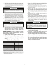
SPT PLUS Sensor
Shown
+12V
Rnet-
Rnet+
Gnd
RED
BLACK
WHITE
GREEN
To WSHP Controller
Rnet Terminals (J13)
FIELD INSTALLED
LEGEND
NOTES:
1. Mount the water source heat pump controller in the equipment controls enclosure
with at least two #6 x 1 in. self-tapping screws. Allow adequate clearance for wiring.
2. Verify sensor power and wiring requirements prior to making any terminations. Sen-
sors requiring a separate isolated 24 vac power source will not utilize WSHP termi-
nals J4-1, or 4.
AI — Analog Input
AO — Analog Output
BI — Binary Input
BO — Binary Output
SPT — Space Temperature
Factory Wiring
Field Wiring