


22
COMPLETE
C
CONTROL
BR
CR
CAP
PB
GROUND
TRANSFORMER
BRN YEL
Y
W
O
G
R
C
AL1
AL2
A
P1
ALARM
RELAY
SEE
NOTE 6
JW1
WV
COMPRESSOR
COOLING
FAN
24 VAC
COMMON
ALARM
CLASS 1 WIRING
REQUIRED INSIDE
CONTROL BOX
Y
O
G
R
C
L
CLASS 1 OR 2
WIRING ACCEPTABLE
OUTSIDE
CONTROL BOX
TYPICAL HEAT PUMP T-STAT
SEE NOTE 5
BRN
YEL
BLU
R
Y
JW3
FP1
JW2
FP2
SEE
NOTE 4
COMPR.
RELAY
STATUS
LED
G
COMPLETE C
MICRO-
PROCESSOR
CONTROL
LOGIC
CO
DIP SWITCH
OFF ON
PM: DISABLED/
ENABLED
STAGE 2: 2/1
NOT USED
NOT USED
FP1/FP2
FAULTS: 3/1
1
2
3
4
5
C
TEST PINS
YEL
HP
LOC
FP1
FP2
RV
CO12
P2
24V
DC
EH1
EH2
P3
HP
LOC
FP1
FP2
RVS
CO
SEE
NOTE 4
RED
RED
BLU
BRN
GRY
GRY
VIO
VIO
BRN
ORG
NOT USED
1
2
3
4
5
6
7
8
9
10
RED
(220V)
ORG (240V)
CB
BLK
TRANS
24V
SEE
NOTE 7
BR BRG CCG
SEE
NOTE 7
CC
YELBRN
10
CR
BRNBRNGRYYEL
BR
DM
BRNYEL
ORGYEL
10
BLK
ORG
230V
24V
TRANS
CB*
POWER SUPPLY
REFER TO DATA PLATE
USE COPPER CONDUCTORS ONLY.
SEE NOTE 2
REFER TO DISCONNECT
BOX FOR OPTIONAL
POWER SUPPLY CONNECTION
GROUND
L2
L1
OPTIONAL
CORD
CONNECTION
RED
NEUTRAL ON 265V
SYSTEMS
L2 (ribbed)
GROUND
L1 (plain)
PB
1
2
H
C
F
CAP
RED
RED
6
8
2
4
BLK
BLK
R
S
C
CR
BLU
COMPRESSOR
BRN
YEL
BLK
2
1
BM
B (HIGH)
A (LOW)
RED
BLK
FSS
1
2
BLK
BR
NO
COM
115
208
230
265
WHT
RED
ORG
BRN
LEAD COLOR
VOLTAGE
TRANSFORMER PRIMARY
LEAD COLORS
SEE
NOTE 3
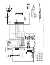
BLOWER MOTOR WIRING
UNIT SIZE POLE A POLE B
09 5 4
12 4 3
15 4 3
18 4 3
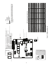
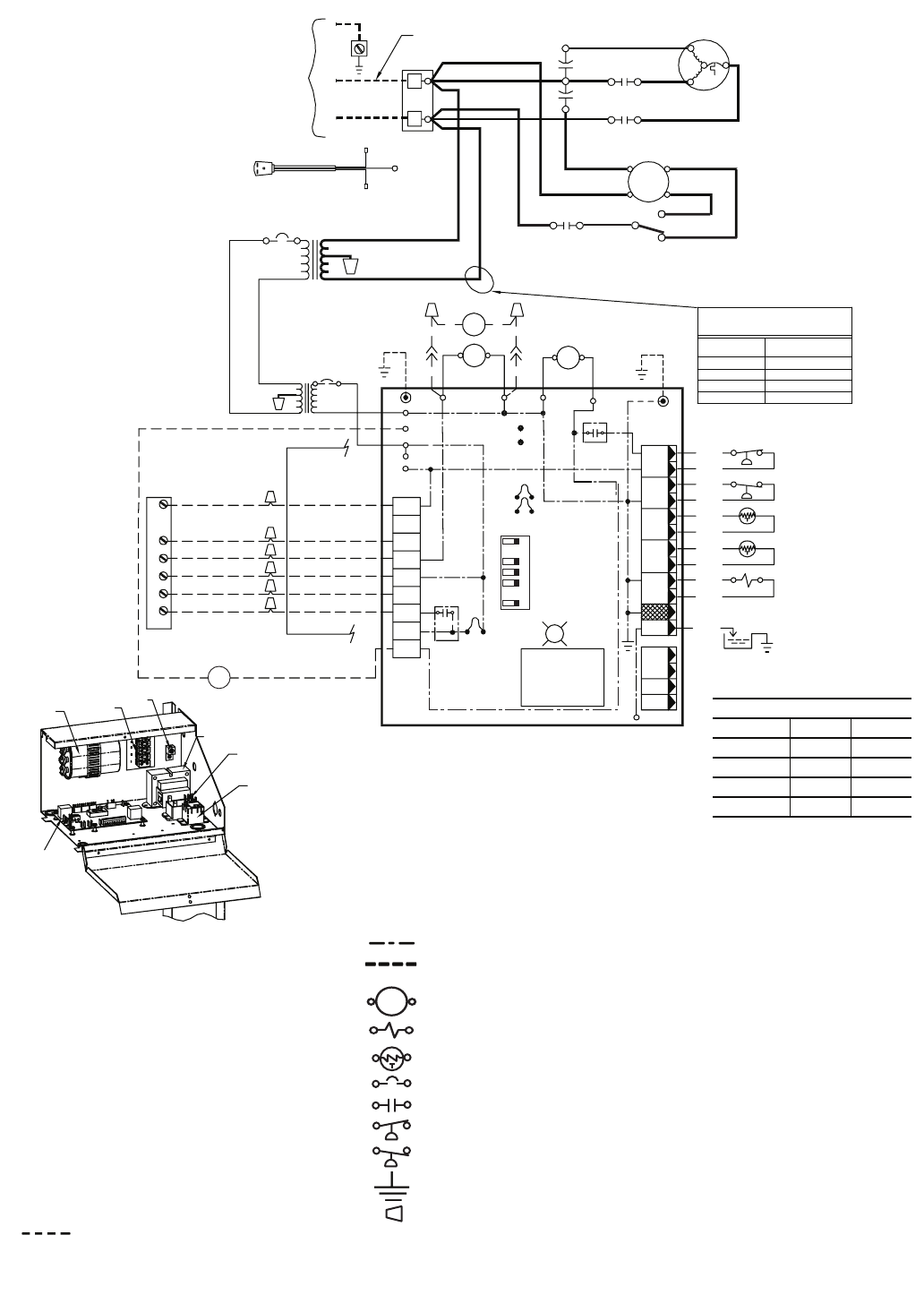
AL — Alarm Relay Contacts
BM — Blower Motor
BR — Blower Relay
CAP — Capacitor
CB — Circuit Breaker
CO — Sensor, Condensate Overflow
CR — Compressor Relay
DM — Damper Motor
FP1 — Sensor, Water Coil Freeze Protection
FP2 — Sensor, Air Coil Freeze Protection
FSS — Fan Speed Switch
HP — High-Pressure Switch
JW1 — Jumper Wire for Alarm
LOC — Loss of Charge Pressure Switch
PB — Power Terminal Block
PM — Performance Monitor
RVS — Reversing Valve Solenoid
TRANS — Transformer
WV — Water Valve
---------- Field Line Voltage Wiring
Field Low-Voltage Wiring
LEGEND
Printed Circuit Trace
Option Low Voltage
Wiring
Relay/Contactor Coil
Solenoid Coil
Thermistor
Circuit Breaker
Relay Contacts-N.O.
Switch-High Pressure
Switch-Low Pressure
Ground
Wire Nut
Mate-N-Lock
>
>
*Optional wiring.
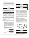
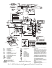
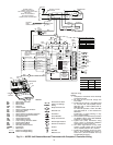
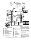
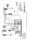
NOTES:
1. Compressor and blower motor thermally
protected internally.
2. All wiring to the unit must comply with
local codes.
3. Transformer is wired to 115-V (WHT) lead
for 115/1/60 units; 265-V (BRN) lead for
265/1/60 units; or 208-V (RED) lead for
208/1/60 units.
For 230/1/60 operation, switch the RED
and ORG leads at L1 and insulate the
RED lead.
Transformer is energy limiting or may
have a circuit breaker.
4. FP1 thermistor provides freeze protection
for WATER. When using ANTI-FREEZE
solutions, cut JW3 jumper.
5. Typical heat pump thermostat wiring
shown. Refer to thermostat Installation
Instructions for wiring to the unit.
6. 24-V alarm signal shown. For dry alarm
contact, cut JW1 jumper and dry contact
will be available between AL1 and AL2.
7. Transformer secondary ground via Com-
plete C board standoffs and screws to
control box. (Ground available from top
two standoffs as shown.)
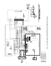
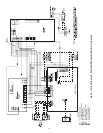
Fig. 21 — 50PEC Unit Remote-Mounted Thermostat with Complete C Controller Wiring