


37
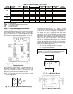
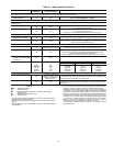
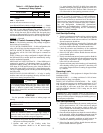
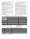
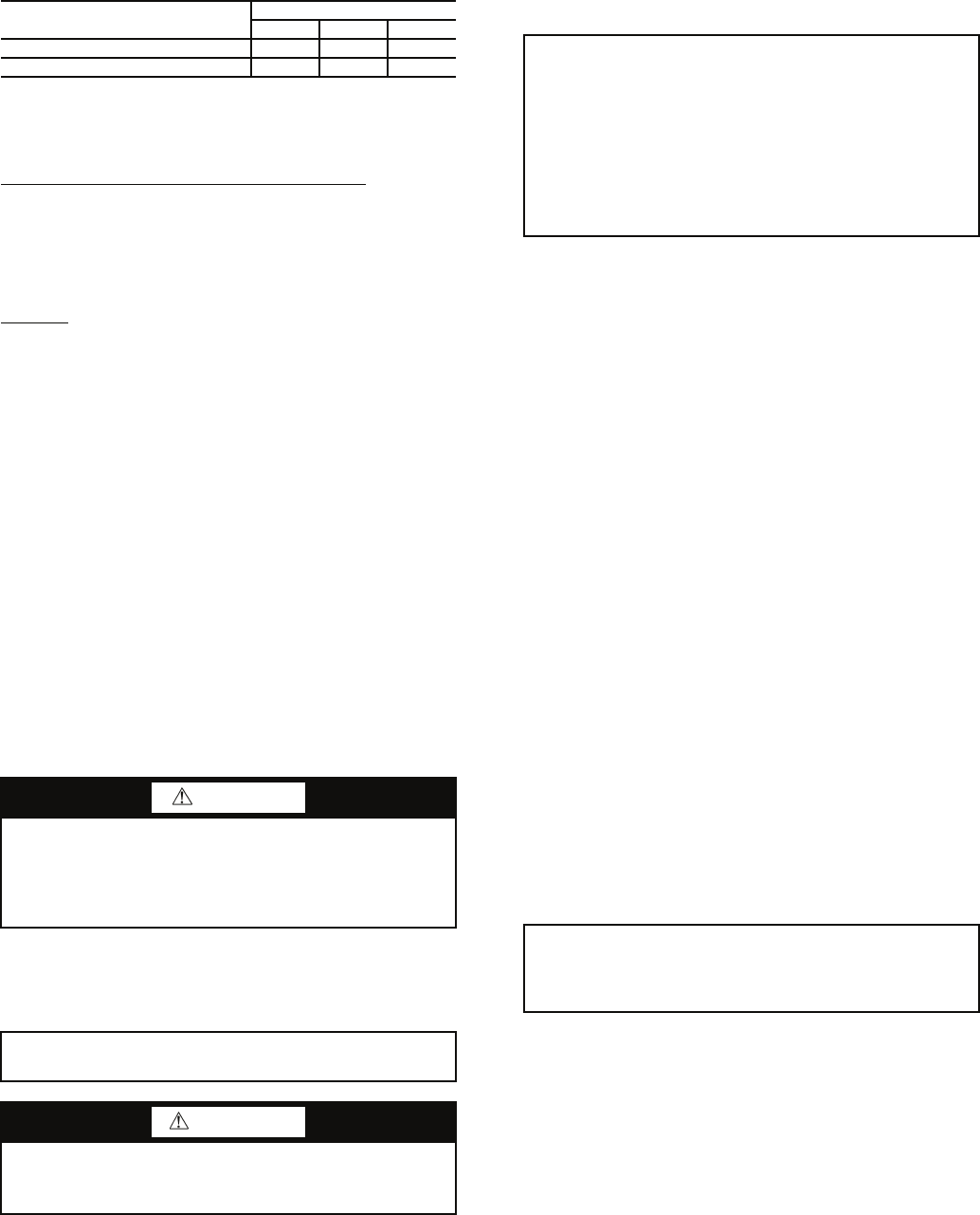
Table 11 — DIP Switch Block S2 —
Accessory 2 Relay Options
LEGEND
NOTE: All other switch combinations are invalid.
Auto Dehumidification Mode or High Fan Mode — Switch
7 provides selection of auto dehumidification fan mode or high
fan mode. In auto dehumidification fan mode, the fan speed
relay will remain off during Cooling Stage 2 if terminal H is
active. In high fan mode, the fan enable and fan speed relays
will turn on when terminal H is active. Set the switch to ON for
auto dehumidification fan mode or to OFF for high fan mode.
Switch 8
— Not used.
Deluxe D Control Accessory Relay Configura-
tions —
The following accessory relay settings are applica-
ble for Deluxe D control only:
CYCLE WITH COMPRESSOR — In this configuration, the
relay will be ON any time the compressor relay is on.
DIGITAL NIGHT SETBACK (NSB) — In this configura-
tion, the relay will be ON if the NSB input is connected to
ground C.
NOTE: If there are no relays configured for digital NSB, then
the NSB and OVR (override) inputs are automatically config-
ured for mechanical operation.
MECHANICAL NIGHT SETBACK — When NSB input is
connected to ground C, all thermostat inputs are ignored. A
thermostat setback heating call will then be connected to the
OVR input. If OVR input becomes active, then the Deluxe D
control will enter night low limit (NLL) staged heating mode.
The NLL staged heating mode will then provide heating during
the NSB period.
WATER VALVE (SLOW OPENING) — If relay is config-
ured for water valve (slow opening), the relay will start 60 sec-
onds prior to starting compressor relay.
START-UP
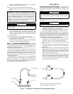
Use the procedure outlined below to initiate proper unit
start-up:
1. Adjust all valves to the full open position and turn on the
line power to all heat pump units.
2. Operate each unit in the Cooling mode first.
Room temperature should be in the normal range
(i.e., approximately 50 to 80 F dry bulb). Loop water tem-
perature entering the heat pumps should be at least 40 F
but not in excess of 110 F. Refer to Table 8 for more spe-
cific information on the operating parameters of units.
Unit Start-Up/Cooling
1. Turn the unit thermostat to the cooling position and turn
the fan speed switch to “HI.” If the unit has an optional
MCO thermostat, set the selector switch to Cool. Both the
fan and compressor should run.
2. Check for cool air delivery at unit grille 15 minutes after
the unit has begun operating. List the identification num-
ber of any machines that do not function at this time.
3. Check the elevation and cleanliness of the condensate
lines; any dripping could be a sign of a blocked line.
4. Select low fan speed. Airflow should decrease and com-
pressor should operate.
5. Slowly turn thermostat toward warmer position. Both fan
and compressor should shut off when thermostat set point
equals room temperature. Room temperature must be
below 90 F for unit to shut off.
6. Operate each heat pump in the heating cycle immediately
after checking cooling cycle operation. A time delay will
prevent the compressor from re-starting for approximate-
ly 5 minutes.
Operating Limits
ENVIRONMENT — This equipment is designed for indoor
installation ONLY.
POWER SUPPLY — A voltage variation of ± 10% of name-
plate utilization voltage is acceptable.
50PEC UNIT STARTING CONDITIONS — The 50PEC
units will start and operate at an ambient temperature of 50 F
with entering-air temperature at 50 F, entering water at 60 F,
and with both air and water at the flow rates used in the
ARI/ISO/ASHRAE Standard 13256-1 rating test, for initial
start-up in winter.
Unit Start-Up/Heating
1. Adjust the unit thermostat to the warmest setting and turn
the fan speed switch to “HI.” If the unit has an optional
MCO thermostat, set the selector switch to Heat. The
blower should start immediately and after the time delay
is complete, the compressor will start.
2. Once the unit has begun to run, check for warm air delivery
at the unit grille. Again, the installing contractor must list
the serial number of any machine that does not function.
3. Log the unit operating conditions at initial start-up for
each unit to establish a permanent operating record.
4. Select low fan speed. Airflow should decrease and com-
pressor should continue to operate.
ACCESSORY 2
RELAY OPTIONS
DIP SWITCH POSITION
456
Digital NSB Off On On
Water Valve — Slow Opening On Off On
NSB — Night Setback
CAUTION
To avoid equipment damage, DO NOT leave system filled
in a building without heat during the winter unless anti-
freeze is added to system water. Condenser coils never
fully drain by themselves and will freeze unless winterized
with antifreeze.
IMPORTANT: This equipment is designed for indoor
installation ONLY.
WARNING
When the disconnect switch is closed, high voltage is
present in some areas of the electrical panel. Exercise cau-
tion when working with the energized equipment.
IMPORTANT: Three factors determine the operating limits
of a unit: (1) return-air temperature, (2) water temperature
and (3) ambient temperature. Whenever any one of these
factors is at a minimum or maximum level, the other two
factors must be at normal levels to ensure proper unit oper-
ation. Flow rates must be at nominal ARI (Air Condition-
ing and Refrigeration Institute)/ISO (International
Organization for Standardization)/ ASHRAE (American
Society of Heating, Refrigerating and Air Conditioning
Engineers) 13256-1 standards.
IMPORTANT: These operating limits are not normal or
continuous operating conditions. It is assumed that such a
start-up is for the purpose of bringing the building space up
to occupancy temperature.