45
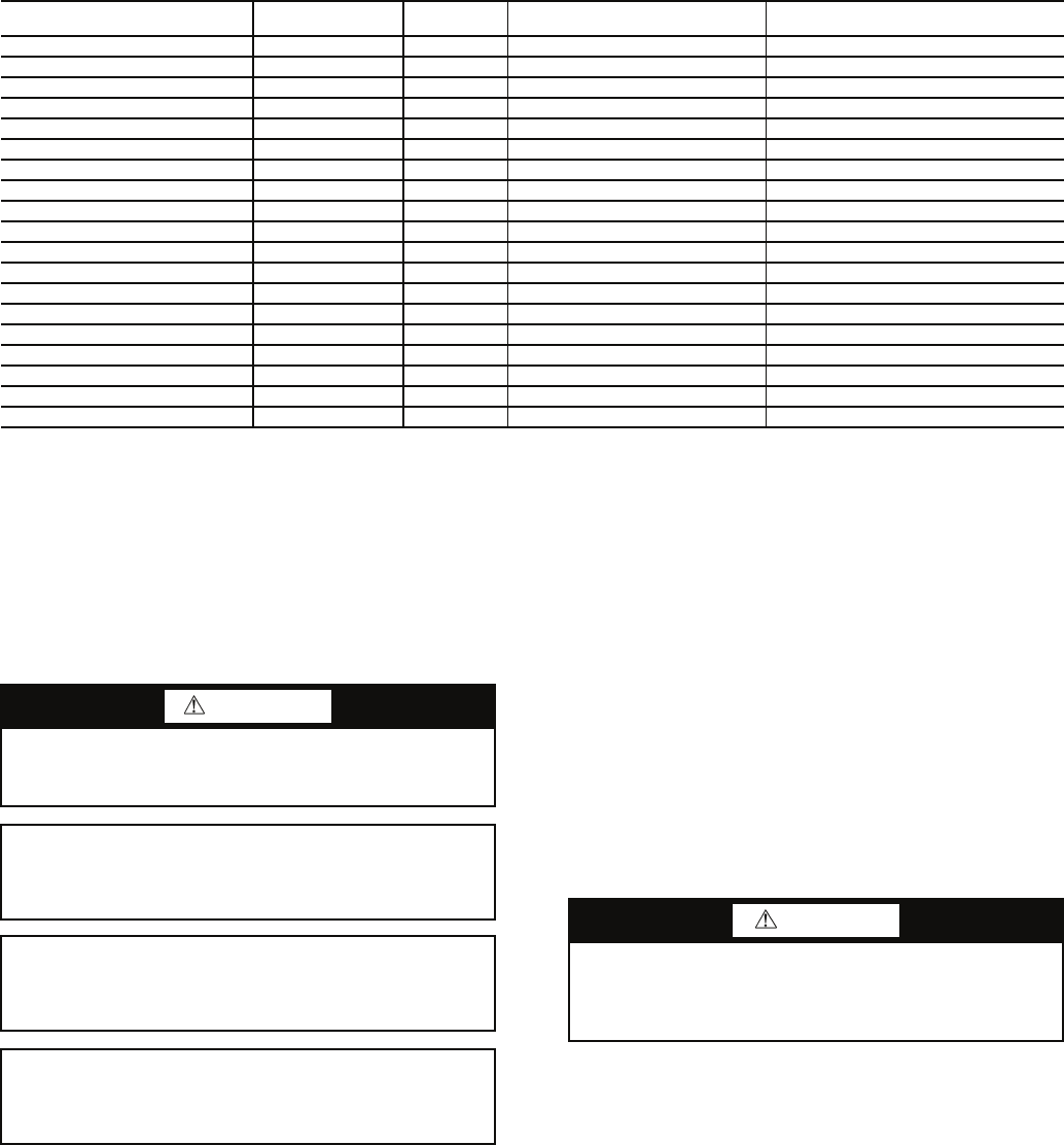
Table 17 — Aquazone™ Deluxe D Control Current LED Status and Alarm Relay Operations
LEGEND NOTES:
1. If there is no fault in memory, the Fault LED will flash code 1.
2. Codes will be displayed with a 10-second Fault LED pause.
3. Slow flash is 1 flash every 2 seconds.
4. Fast flash is 2 flashes every 1 second.
5. EXAMPLE: “Flashing Code 2” is represented by 2 fast flashes followed
by a 10-second pause. This sequence will repeat continually until the
fault is cleared.
SERVICE
Perform the procedures outlined below periodically, as
indicated.
Unit Inspection — Visually inspect the unit at least once
a month. Pay special attention to hose assemblies. Repair any
leaks and replace deteriorated hoses immediately. Note any
signs of deterioration or cracking.
System Flushing — Properly clean and flush system
periodically. Refer to Pre-Start-Up, System Cleaning and
Flushing section.
Water Coil — Keep air out of the water coil. Check open
loop systems to be sure the well head is not allowing air to in-
filtrate the water line. Always keep lines airtight.
Inspect heat exchangers regularly and clean more frequently
if the unit is located in a “dirty” environment. The heat
exchanger should be kept full of water at all times. Open loop
systems should have an inverted P trap placed in the discharge
line to keep water in the heat exchanger during off cycles.
Closed loop systems must have a minimum of 15 psig during
the summer and 40 psig during the winter.
Check P trap frequently for proper operation.
FILTERS — Inspect filters. Establish a regular maintenance
schedule. Clean or replace filters frequently depending on
need.
To remove the filter from the 50PEC unit, slide the filter out
of its frame located in the return air opening at the bottom front
of the unit. When re-installing the filter, use the slide-in rails of
the filter frame to guide the filter into the proper position.
Refrigerant System — Verify air and water flow rates
are at proper levels before servicing. To maintain sealed circuit-
ry integrity, do not install service gages unless unit operation
appears abnormal.
Condenser Cleaning — Water-cooled condensers may
require cleaning of scale (water deposits) due to improperly
maintained closed-loop water systems. Open water tower
systems may require removal of sludge build-up due to
induced contaminants.
Local water conditions may cause excessive fouling or
pitting of tubes. Therefore, condenser tubes should be cleaned
at least once a year, or more often if the water is contaminated.
Use standard coil cleaning procedures which are compatible
with both the heat exchanger material and copper water lines.
Generally, the more water flowing through the unit, the less
chance for scaling, however flow rates over 3 gpm per ton can
DESCRIPTION
STATUS LED
(Green)
TEST LED
(Yellow)
FAULT LED (Red) ALARM RELAY
Normal Mode On Off Flash Last Fault Code in Memory Open
Normal Mode with PM On Off Flashing Code 8 Cycle (closed 5 sec, open 25 sec, …)
D Control is non-functional Off Off Off Open
Test Mode — On Flash Last Fault Code in Memory Cycling Appropriate Code
Night Setback Flashing Code 2 — Flash Last Fault Code in Memory —
ESD Flashing Code 3 — Flash Last Fault Code in Memory —
Invalid T-stat Inputs Flashing Code 4 — Flash Last Fault Code in Memory —
No Fault in Memory On Off Flashing Code 1 Open
HP Fault Slow Flash Off Flashing Code 2 Open
LP Fault Slow Flash Off Flashing Code 3 Open
FP1 Fault Slow Flash Off Flashing Code 4 Open
FP2 Fault Slow Flash Off Flashing Code 5 Open
CO Fault Slow Flash Off Flashing Code 6 Open
Over/Under Voltage Slow Flash Off Flashing Code 7 Open (closed after 15 minutes)
HP Lockout Fast Flash Off Flashing Code 2 Closed
LP Lockout Fast Flash Off Flashing Code 3 Closed
FP1 Lockout Fast Flash Off Flashing Code 4 Closed
FP2 Lockout Fast Flash Off Flashing Code 5 Closed
CO Lockout Fast Flash Off Flashing Code 6 Closed
CO — Condensate Overflow LED — Light-Emitting Diode
ESD — Emergency Shutdown LP — Low Pressure
FP — Freeze Protection PM — Performance Monitor
HP — High Pressure
WARNING
To prevent injury or death due to electrical shock or contact
with moving parts, open unit disconnect switch before ser-
vicing unit.
IMPORTANT: When a compressor is removed from this
unit, system refrigerant circuit oil will remain in the com-
pressor. To avoid leakage of compressor oil, the refrigerant
lines of the compressor must be sealed after it is removed.
IMPORTANT: All refrigerant discharged from this unit
must be recovered without exception. Technicians must fol-
low industry accepted guidelines and all local, state and fed-
eral statutes for the recovery and disposal of refrigerants.
IMPORTANT: To avoid the release of refrigerant into the
atmosphere, the refrigerant circuit of this unit must only be
serviced by technicians who meet local, state and federal
proficiency requirements.
CAUTION
To avoid fouled machinery and extensive unit clean-up,
DO NOT operate units without filters in place. DO NOT
use equipment as a temporary heat source during
construction.


