


39
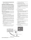
b. Select Weekly, then press enter (7 schedules
available).
c. Select day and press enter.
d. Press enter again and select ADD or DEL (DECR
or INCR) set schedule.
e. Enter ON/OFF time, then press continue.
f. Press OK to apply and save to a particular day of
the week.
g. Continue to add the same or different schedule spe-
cific days of the week.
To add exceptions to the schedule:
i. Press Add softkey.
ii. Select exception type from following:
• Date
• Date Range
• Week-N-Day
• Calender Reference
9. Go back to Home Screen.
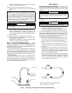
10. Remove BACview
6
cable from SPT sensor by reversing
the process in Step 1.
11. Perform system test.
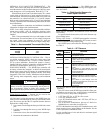
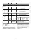
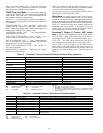
Flow Regulation — Flow regulation can be accom-
plished by two methods. Most water control valves have a
built-in flow adjustment valve. Determine the flow rate by
measuring the pressure drop through the unit heat exchanger.
See Table 12. Adjust the water control valve until a flow of 1.5
to 2 gpm per ton cooling is achieved. Since the pressure
constantly varies, two pressure gages may be needed.
An alternative method for regulating flow is to install a flow
control device. These devices are typically an orifice of plastic
material mounted on the outlet of the water control valve,
designed to allow a specified flow rate. Occasionally these
valves produce a velocity noise that can be reduced by
applying some back pressure. To accomplish this, slightly close
the leaving isolation valve of the water regulating device.
Antifreeze — In areas where entering loop temperatures
drop below 40 F or where piping will be routed through areas
subject to freezing, antifreeze is needed.
Alcohols and glycols are commonly used as antifreeze
agents. Freeze protection should be maintained to 15 F below the
lowest expected entering loop temperature. For example, if the
lowest expected entering loop temperature is 30 F, the leaving
loop temperature would be 22 to 25 F. Therefore, the freeze pro-
tection should be at 15 F (30 F –15 F) = 15 F.
Calculate the total volume of fluid in the piping system. See
Table 13. Use the percentage by volume in Table 14 to deter-
mine the amount of antifreeze to use. Antifreeze concentration
should be checked from a well mixed sample using a hydrome-
ter to measure specific gravity.
FREEZE PROTECTION SELECTION — The 30 F FP1 fac-
tory setting (water) should be used to avoid freeze damage to
the unit.
Once antifreeze is selected, the JW3 jumper (FP1) should
be clipped on the control to select the low temperature
(antifreeze 10 F) set point to avoid nuisance faults.
Table 12 — Coaxial Water Pressure Drop
LEGEND
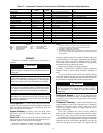
CAUTION
DO NOT use “Stop Leak” or any similar chemical agent in
this system. Addition of these chemicals to the loop water
will foul the system and inhibit unit operation.
IMPORTANT: All alcohols should be pre-mixed and
pumped from a reservoir outside of the building or intro-
duced under water level to prevent alcohols from fuming.
UNIT
50PEC
FLOW
(GPM)
PRESSURE DROP (ft wg)
30 F 50 F 70 F 90 F
Without
Motorized
Valve
With Cv = 2.9
MOPD = 125 psi
Without
Motorized
Valve
With Cv = 2.9
MOPD = 125 psi
Without
Motorized
Valve
With Cv = 2.9
MOPD = 125 psi
Without
Motorized
Valve
With Cv = 2.9
MOPD = 125 psi
09
1.3 1.8 2.0 1.3 1.5 1.2 1.3 1.0 1.2
1.9 3.2 3.6 2.5 2.9 2.2 2.7 2.0 2.4
2.5 5.0 5.8 3.9 4.6 3.5 4.2 3.0 3.8
12
1.6 1.8 6.5 1.6 6.5 1.4 6.5 1.3 6.5
2.3 3.3 11.4 2.9 11.4 2.6 11.4 2.3 11.4
3.1 5.3 19.6 4.5 19.6 4.1 19.6 3.7 19.6
15
1.8 1.2 1.6 1.2 1.6 1.1 1.5 1.0 1.4
2.7 2.6 3.4 2.2 3.1 2.0 2.9 1.9 2.7
3.6 4.2 5.7 3.5 5.0 3.2 4.8 3.0 4.5
18
2.4 2.1 2.8 2.0 2.6 1.8 2.4 1.6 2.3
3.6 4.2 5.8 3.7 5.2 3.3 4.9 3.0 4.6
4.8 6.8 9.6 6.0 8.8 5.5 8.2 4.9 7.7
Cv — Flow Coefficient
MOPD — Maximum Operating Pressure Differential