


32
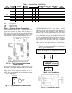
Table 6 — Rnet Wiring Specifications
LEGEND
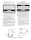
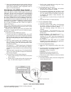
To wire the SPT sensor to the controller:
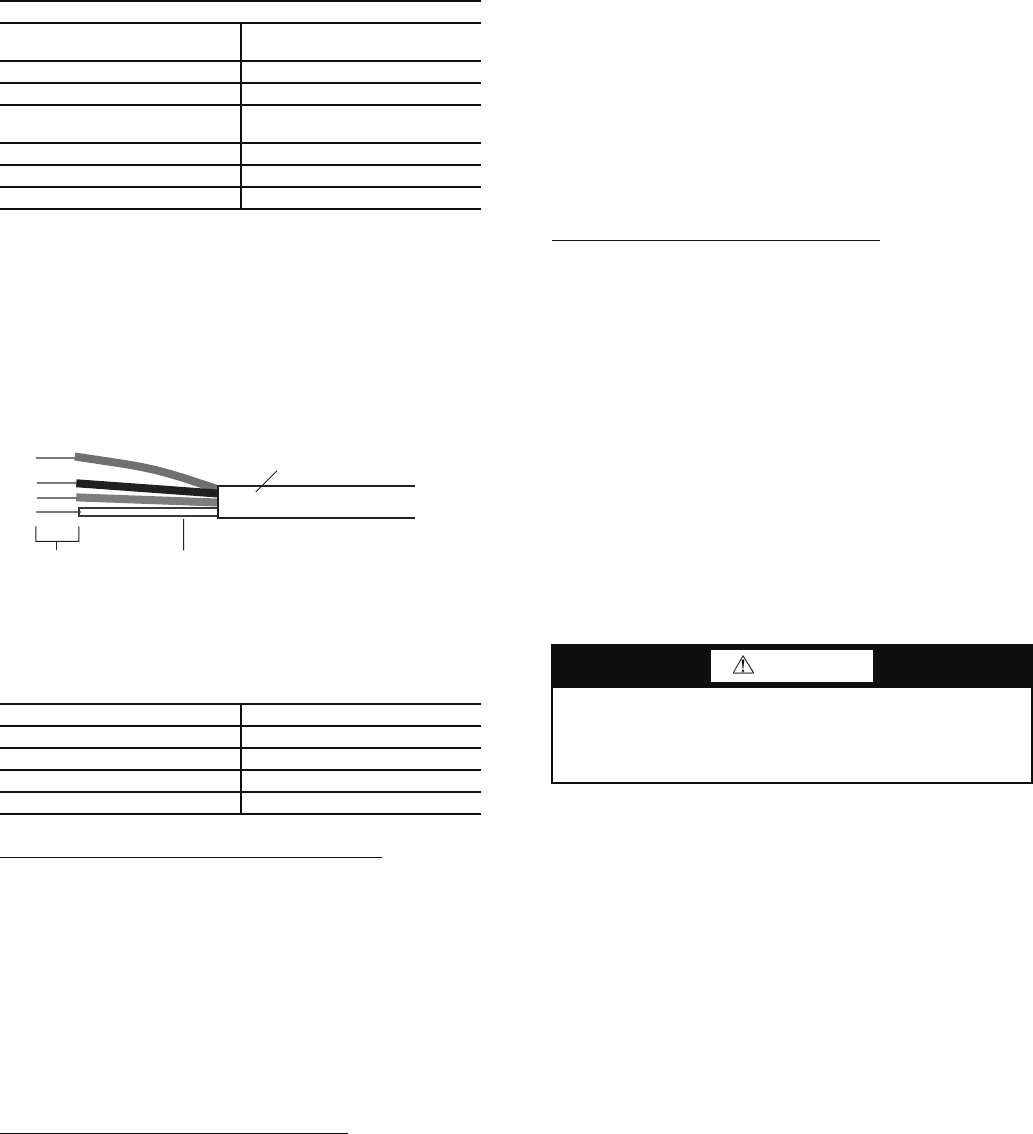
1. Partially cut , then bend and pull off the outer jacket of
the Rnet cable(s), being careful not to nick the inner
insulation.
2. Strip about
1
/
4
in. of the inner insulation from each wire.
See Fig. 34.
3. Wire each terminal on the sensor to the same terminal on
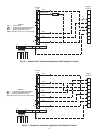
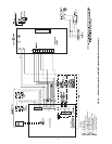
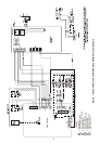
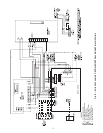
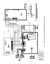
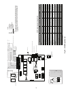
the controller. See Fig. 25-29. Table 7 shows the recom-
mended Rnet wiring scheme.
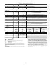
Table 7 — Rnet Wiring
NOTE: The wire should be connected to the terminal shown.
Wiring a Supply Air Temperature (SAT) Sensor — The
SAT sensor is required for reheat applications.
If the cable used to wire the SAT sensor to the controller
will be less than 100 ft, an unshielded 22 AWG (American
Wire Gage) cable should be used. If the cable will be greater
than 100 ft, a shield 22 AWG cable should be used. The cable
should have a maximum length of 500 ft.
To wire the SAT sensor to the controller:
1. Wire the sensor to the controller. See Fig. 25-29.
2. Verify that the Enable SAT jumper is on.
3. Verify that the Enable SAT and Remote jumper is in the
left position.
Wiring an Indoor Air Quality (IAQ) Sensor
— An IAQ
sensor monitors CO
2
levels. The WSHP Open controller uses
this information to adjust the outside-air dampers to provide
proper ventilation. An IAQ sensor can be wall-mounted or
mounted in a return air duct. (Duct installation requires an aspi-
rator box assembly.)
The sensor has a range of 0 to 2000 ppm and a linear 4 to
20 mA output. This is converted to 1 to 5 vdc by a 250-ohm,
1
/
4
watt, 2% tolerance resistor connected across the zone con-
troller’s IAQ input terminals.
NOTE: Do not use a relative humidity sensor and CO
2
sensor
on the same zone controller if both sensors are powered off the
board. If sensors are externally powered, both sensors may be
used on the same zone controller.
If the cable used to wire the IAQ sensor to the controller
will be less than 100 ft, an unshielded 22 AWG (American
Wire Gage) cable should be used. If the cable will be greater
than 100 ft, a shield 22 AWG cable should be used. The cable
should have a maximum length of 500 ft.
To wire the IAQ sensor to the controller:
1. Wire the sensor to the controller. See Fig. 25-29.
2. Install a field-supplied 250-ohm,
1
/
4
watt, 2% tolerance
resistor across the controller’s RH/IAQ and Gnd
terminals.
3. Verify the the RH/IAQ jumper is set to 0 to 5-vdc.
Wiring a Relative Humidity (RH) Sensor
— The RH sensor
is used for zone humidity control (dehumidification) if the
WSHP unit has a dehumidification device. If not, the sensor
only monitors humidity.
NOTE: Do not use a relative humidity sensor and CO
2
sensor
on the same zone controller if both sensors are powered off the
board. If sensors are externally powered, both sensors may be
used on the same zone controller.
If the cable used to wire the RH sensor to the controller will
be less than 100 ft, an unshielded 22 AWG (American Wire
Gage) cable should be used. If the cable will be greater than
100 ft, a shield 22 AWG cable should be used. The cable
should have a maximum length of 500 ft.
To wire the RH sensor to the controller:
1. Strip the outer jacket from the cable for at least 4 inches.
2. Strip
1
/
4
in. of insulation from each wire.
3. Wire the sensor to the controller.
Step 6 — Install Supply and Return Piping
SUPPLY AND RETURN HOSES — Optional pressure-rated
hose assemblies are available for use with units. Use the fol-
lowing guidelines when installing supply and return hose
assemblies.
1. Install supply and return hoses fitted with swivel-joint
fittings at one end to prevent the hose from twisting.
2. Use male adapters to secure the hose assembly to the unit
and the riser.
3. Do not allow the hose to twist during installation. Twist-
ing may damage the hose wall or the rubber compound.
4. Use pipe joint compound sparingly on the fitting adapt-
ers’ male pipe threads.
5. Prevent sealant from reaching the joint’s flared surfaces.
6. Do not use pipe joint compound when Teflon* thread
tape is pre-applied to hose assemblies or when flared-end
connections are used.
7. Maximum torque that may be applied to brass fittings is
30 ft-lb. When a torque wrench is not used, tighten brass
fittings finger-tight plus one quarter turn.
8. Tighten steel fittings as necessary.
9. Use shut-off/balancing valves, flow indicators, and drain
tees in the supply runout and return at each floor to aid in
loop balancing and servicing.
SUPPLY AND RETURN PIPING — System piping MUST
comply with all applicable codes.
1. Install a drain valve at the base of each supply and return
riser to enable system flushing at start-up and during rou-
tine servicing.
RNET WIRING SPECIFICATIONS
Description
4 conductor, unshielded, CMP,
plenum rated cable
Conductor 18 AWG
Maximum Length 500 ft
Recommended Coloring
Jacket: white
Wiring: black, white, green, red
UL Temperature 32 to 167 F
Voltage 300-vac, power limited
Listing UL: NEC CL2P, or better
AWG — American Wire Gage
CMP — Communications Plenum Cable
NEC — National Electrical Code
UL — Underwriters Laboratories
WIRE TERMINAL
Red +12-v
Black .Rnet
White Rnet+
Green Gnd
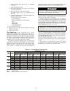
Fig. 34 — Rnet Cable Wire
OUTER JACKET
INNER INSULATION
.25 IN.
a50-8443
–
CAUTION
To ensure proper functioning of unit and system, be sure to
connect entering water to upper pipe on right-hand units.
On left-hand units, connect entering water to lower pipe.
Failure to do so could result in equipment damage.
*Teflon is a trademark of E. I. du Pont de Nemours and Company.