


16
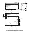
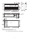
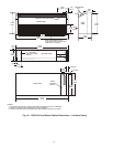
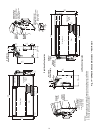
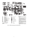
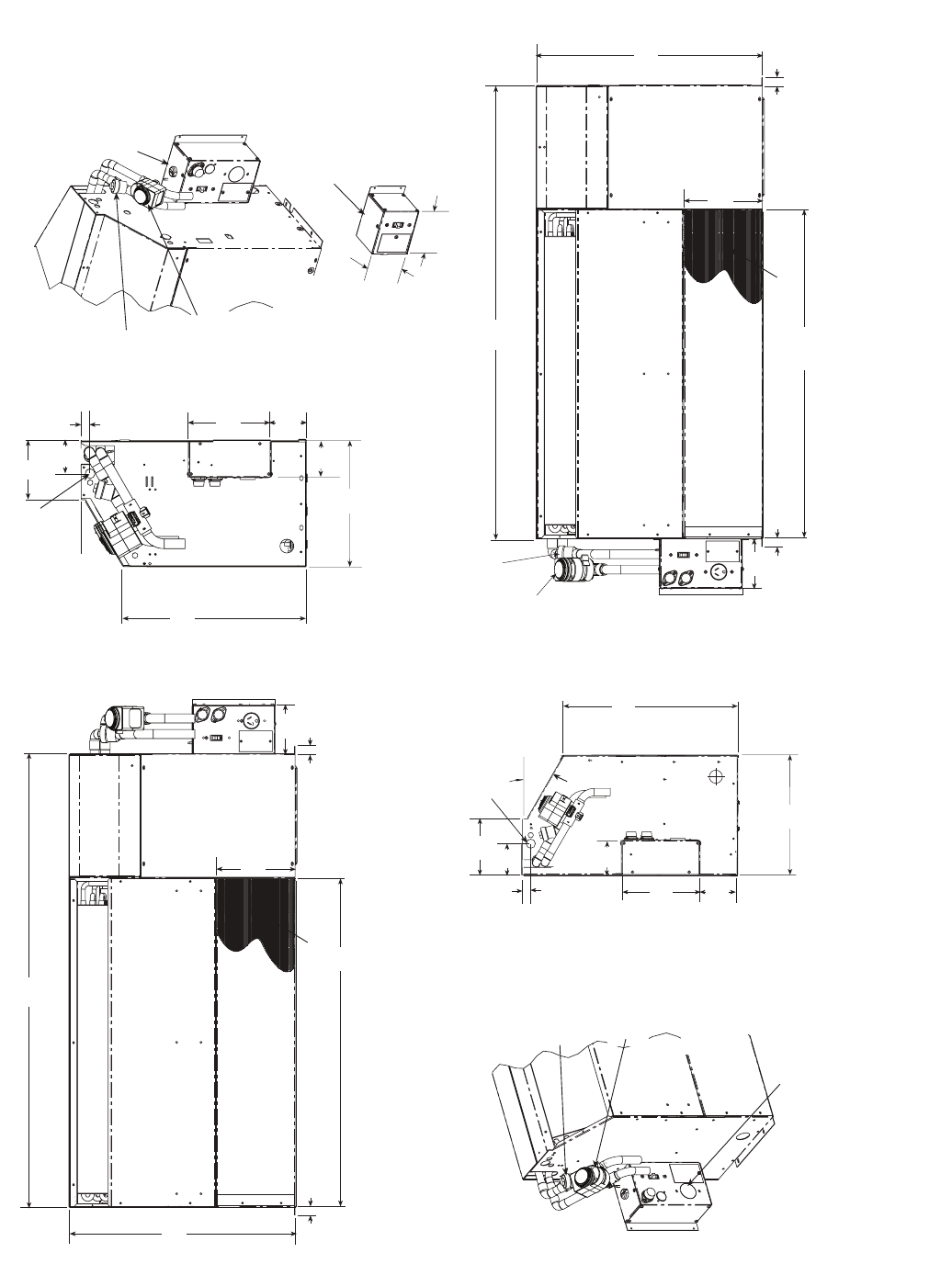
Fig. 14 — 50PEC18 Chassis Dimensions — Front Return
NOTES:
1. Dimensions shown are in inches. Dimensions in parentheses are in millimeters.
2. Optional autoflow valve, motorized water valve and disconnect box are shown.
3. Chassis can mount directly on floor.
Blower Deck
Compressor
Access
Panel
Control Box
46.98
(1193)
4.49
(114)
0.75
(19)
0.75
(19)
20.50
(521)
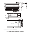
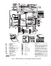
Hard Wire
Power Supply
Blower Deck
Filter
Compressor
Access
Panel
Control Box
0.75
(19)
0.75
(19)
4.46
(113)
20.50
(521)
46.98
(1193)
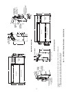
Optional
Motorized
Water Valve
Optional
Autoflow
Valve
Optional
Disconnect Box
(mounted to cabinet
not chassis)
Optional
Motorized
Water Valve
Optional
Autoflow
Valve
7.5
(191)
0.87
(22)
11.54
(293)
3.43
(87)
16.66
(423)
30˚
3.01
(76)
3.56
(90)
11.54
(293)
16.66
(423)
30˚
0.87
(22)
3.01
(76)
5.36
(136)
7.50
(191)
3.42
(87)
3.56
(90)
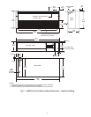
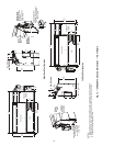
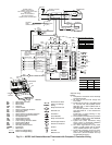
Optional
Motorized
Water Valve
Optional
Autoflow
Valve
Optional Disconnect
Only Box (All Configurations)
Power supply enters
Bottom of Box
4.46
(113)
4.56
(116)
Optional Fused
Disconnect Box
(mounted to cabinet
not chassis)
Power supply enters
Bottom of Box
Power supply enters
Bottom of Box
Hard Wire
Power Supply
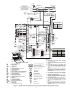
Blower Screen
Blower Screen
Filter
36.00
(914)
7.38
(187)
5.36
(187)
7.38
(187)
36.00
(914)
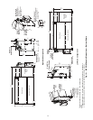
Right Hand Configuration
Left Hand Configuration
a50-8350