


33
2. Install shut-off/balancing valves and unions at each unit
to allow unit removal for servicing.
NOTE: If flex hoses are used, unions are not necessary.
3. Install strainers at the inlet of each system circulating
pump.
4. Before making the final water connections, flush the sys-
tem as described in the Pre-Start-Up section of this
manual. After flushing the system, connect piping and
hoses to the proper supply, return and condensate connec-
tions of the unit.
NOTE: When necessary, use adapters to connect hoses.
5. Install any other system components, as required, follow-
ing manufacturer’s instructions.
6. Reinstall the front cabinet by carefully lowering the front
cabinet over the chassis onto the backplate.
Step 7 — Install Condensate Piping — Connect
the unit condensate drain to the building condensate drain with
a flexible, nonpressure-rated
5
/
8
-in. (16 mm) ID plastic hose.
Avoid kinks in this hose to ensure an unobstructed flow of con-
densate from the unit to the drain.
The horizontal run of the condensate hose is usually too
short to pose any drainage problems, however, the horizontal
run of condensate line should be pitched at least 1 in. for every
10 ft of run (in the direction of flow). Avoid low points and un-
pitched piping since dirt collects in these areas and may cause
stoppage and overflow.
Field installation of a trap or vent is not required unless
specified by local codes. The 50PEC units are designed in a
blow-thru configuration. The condensate drain pan is located
on the outlet side of the blower so that the pressure in the drain
pan is higher than the atmospheric pressure.
PRE-START-UP
System Cleaning and Flushing —
Cleaning and
flushing the unit and system is the single most important step to
ensure proper start-up and continued efficient operation of the
system.
Follow the instructions below to properly clean and flush
the system:
1. Verify that electrical power to the units is disconnected,
and that the circulation pump is deenergized.
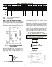
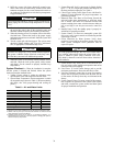
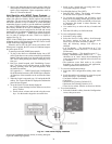
2. Connect the supply hose directly to the return riser valve.
Use a single length of flexible hose, as shown in Fig. 35.
NOTE: If the length of hose is too short (i.e., the resulting con-
nection would exceed the minimum bend radius of the hose),
substitute two lengths of flexible hose joined together with a
field-supplied, standard NPT coupling and the flare-fitting-to-
pipe adapters provided with the hose kit (Fig. 35).
3. Open all air vents. Fill the system with water. Do not al-
low system to overflow. Bleed all air from the system.
Check the system for leaks and repair appropriately.
4. Check and adjust the water and air level in the expansion
tank.
5. Verify all strainers are in place. Start the pumps, and sys-
tematically check each vent to ensure all air is bled from
the system.
6. Verify make-up water is available. Adjust make-up water
appropriately to replace the air that was bled from the
system. Pressure test and inspect the system for leaks and
make any necessary repairs. Check and adjust the water
and air level in the expansion tank.
7. Open a drain at the lowest point in the system. Adjust the
make-up water replacement rate to equal the rate of bleed.
Continue to bleed the system until the water appears
clean or for at least three hours, whichever is longest;
then, completely drain the system.
IMPORTANT: Since loop temperatures are normally
between 60 and 90 F, pipe sweating and heat loss do not
occur at normal ambient temperature conditions. Insulation
must be installed on loop water piping on those sections
that run through unheated areas or are located outside the
building. If loop temperatures are expected below the
ambient dew point, the optional internal insulation
(extended range) package must be ordered.
CAUTION
DO NOT bend or kink supply lines or hoses. Damage to
unit may result.
WARNING
To prevent injury or death due to electrical shock or contact
with moving parts, open unit disconnect before servicing
unit.
CAUTION
DO NOT FLUSH SYSTEM THROUGH THE UNIT!
1/2” Flexible Hose
Brass Adapter
(1/2” MPT x 1/2”
Male Flare)
Supply Valve
Floor Line
Return Valve
Fig. 35 — Temporary Connection for Flushing System Piping
NOTE: Use standard coupling (field-supplied)
and hose adapters to join 2 hoses.