


20
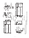
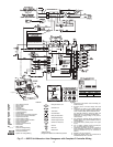
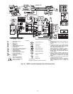
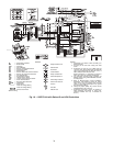
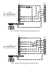
*Optional wiring.
AL — Alarm Relay Contacts
BM — Blower Motor
CAP — Capacitor
CB — Circuit Breaker
CO — Sensor, Condensate Overflow
CR — Compressor Relay
DM — Damper Motor
FP1 — Sensor, Water Coil Freeze Protection
FP2 — Sensor, Air Coil Freeze Protection
FSS — Fan Speed Switch
HP — High-Pressure Switch
JW1 — Jumper Wire for Alarm
LOC — Loss of Charge Pressure Switch
PB — Power Terminal Block
RVS — Reversing Valve Solenoid
TRANS — Transformer
WV — Water Valve
---------- Field Line Voltage Wiring
Field Low-Voltage Wiring
Printed Circuit Trace
LEGEND
Relay/Contactor Coil
Solenoid Coil
Thermistor
Circuit Breaker
Relay Contacts-N.O.
Switch-Temperature
Switch-High Pressure
Switch-Low Pressure
Ground
Wire Nut
Mate-N-Lock
>
>
NOTES:
1. Compressor and blower motor thermally pro-
tected internally.
2. All wiring to the unit must comply with local
codes.
3. Transformer is wired to 115-V (WHT) lead for
115/1/60 units, 265-V (BRN) lead for 265/1/60
units, 240-V (ORG) lead for 240/1/50 units, or
208-V (RED) lead for 208/1/60 units.
Rewire transformer L1 connection if voltage is
230-1-60 or 220-1-50, insulate unused lead.
4. FP1 thermistor provides freeze protection for
WATER. When using ANTI-FREEZE solutions,
cut JW3 jumper.
5. Refer to Microprocessor Control Installation,
Application, and Operation manual for control
wiring to the unit. Low voltage wiring must be
“class 1” and voltage rated equal to or greater
than unit supply voltage.
6. Factory-cut jumper (JW4). Dry contact will be
available between AL1 and AL2.
7. Transformer secondary ground via Deluxe D
board standoffs and screws to control box.
(Ground available from top 2 standoffs as
shown.)
DELUXE D
DELUXE D
a50-8328
Fig. 19 — 50PEC Unit with Deluxe D and LON Controllers