


15
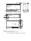
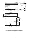
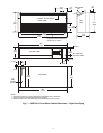
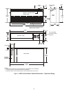
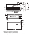
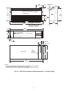
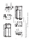
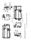
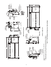
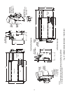
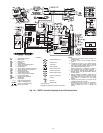
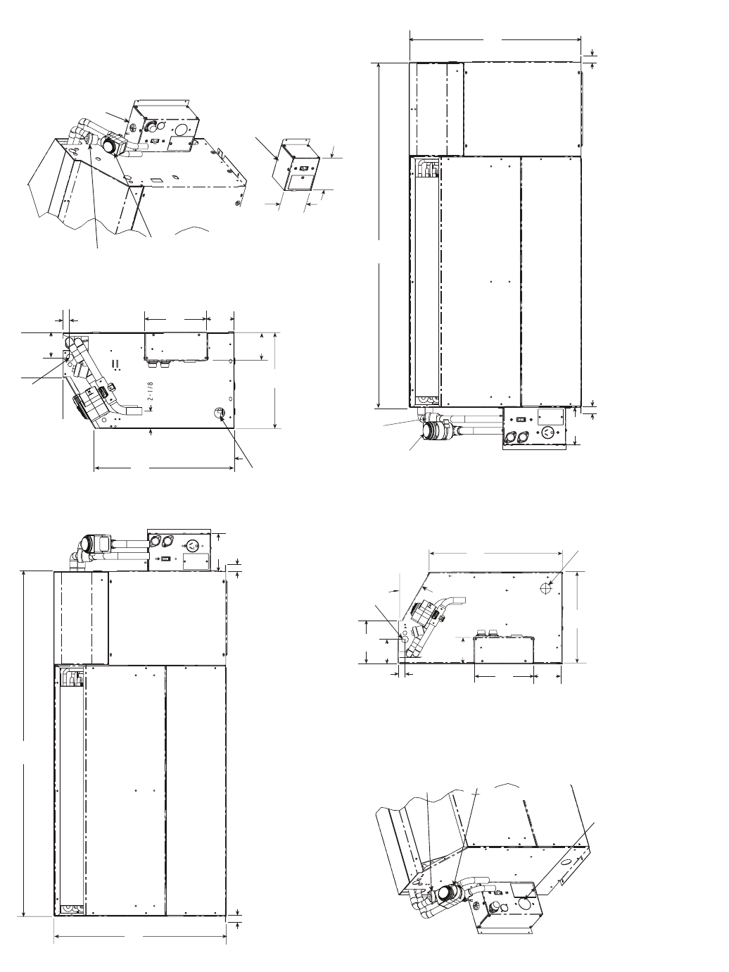
Fig. 13 — 50PEC18 Chassis Dimensions — Bottom Return
*If optional subbase is selected, add 4.9 in. to dimension.
NOTES:
1. Dimensions shown are in inches. Dimensions in parentheses are in millimeters.
2. Optional autoflow valve, motorized water valve and disconnect box are shown.
Blower Deck
Blower Access Panel
Compressor
Access
Panel
Control Box
46.98
(1193)
4.49
(114)
0.75
(19)
0.75
(19)
*20.50
(521)
Hard Wire
Power Supply
Blower Deck
Blower Access Panel
Compressor
Access
Panel
Control Box
0.75
(19)
0.75
(19)
4.46
(113)
*
20.50
(521)
46.98
(1193)
Condensate
5/8" ID V
(15.8mm)
inyl Hose
Optional
Motorized
Water Valve
Optional
Autoflow
Valve
Optional
Disconnect Box
(mounted to cabinet
not chassis)
Optional
Motorized
Water Valve
Optional
Autoflow
Valve
7.5
(191)
0.87
(22)
11.54
(293)
3.43
(87)
*16.66
(423)
30˚
3.01
(76)
(136)
*
3.56
(90)
11.54
(293)
*16.66
(423)
30˚
0.87
(22)
3.01
(76)
5.36
(136)
Condensate
5/8" ID Vinyl Hose
7.50
(191)
3.42
(87)
*
3.56
(90)
Optional
Motorized
Water Valve
Optional
Autoflow
Valve
Optional Disconnect
Only Box (All Configurations)
Power supply enters
Bottom of Box
4.46
(113)
4.56
(116)
Optional Fused
Disconnect Box
(mounted to cabinet
not chassis)
Power supply enters
Bottom of Box
Power supply enters
Bottom of Box
Hard Wire
Power Supply
Right Hand Configuration
Left Hand Configuration
a50-8349