


40
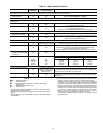
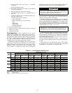
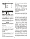
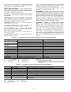
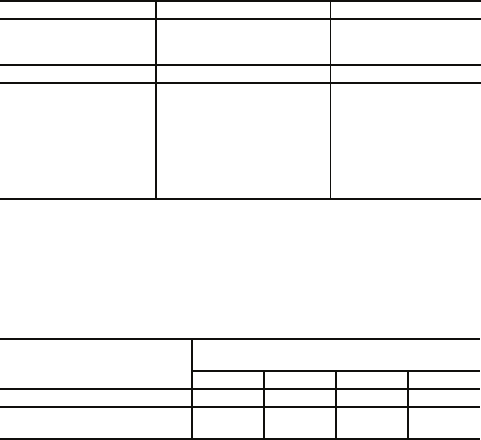
Table 13 — Approximate Fluid Volume (gal)
per 100 ft of Pipe
LEGEND
NOTE: Volume of heat exchanger is approximately 1.0 gallon.
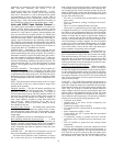
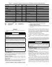
Table 14 — Antifreeze Percentages by Volume
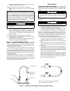
Cooling Tower/Boiler Systems — These systems
typically use a common loop maintained at 60 to 90 F. Carrier
recommends using a closed circuit evaporative cooling tower
with a secondary heat exchanger between the tower and the
water loop. If an open type cooling tower is used continuously,
chemical treatment and filtering will be necessary.
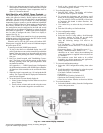
Ground Coupled, Closed Loop and Plateframe
Heat Exchanger Well Systems — These systems al-
low water temperatures from 30 to 110 F. The external loop
field is divided up into 2 in. polyethylene supply and return
lines. Each line has valves connected in such a way that upon
system start-up, each line can be isolated for flushing using only
the system pumps. Air separation should be located in the pip-
ing system prior to the fluid re-entering the loop field.
OPERATION
Power Up Mode —
The unit will not operate until all the
inputs, terminals and safety controls are checked for normal
operation.
NOTE: The compressor will have a 5-minute anti-short cycle
delay upon power up.
Units with Aquazone™ Complete C Control
STANDBY — The Y and W terminals are not active in Stand-
by mode, however the O and G terminals may be active, de-
pending on the application. The compressor will be off.
COOLING — The Y and O terminals are active in Cooling
mode. After power up, the first call to the compressor will ini-
tiate a 5 to 80-second random start delay and a 5-minute anti-
short cycle protection time delay. After both delays are com-
plete, the compressor is energized.
NOTE: On all subsequent compressor calls the random start
delay is omitted.
HEATING STAGE 1 — Terminal Y is active in Heating
Stage 1. After power up, the first call to the compressor will
initiate a 5 to 80-second random start delay and a 5-minute
anti-short cycle protection time delay. After both delays are
complete, the compressor is energized.
NOTE: On all subsequent compressor calls the random start
delay is omitted.
HEATING STAGE 2 — To enter Stage 2 mode, terminal W is
active (Y is already active). Also, the G terminal must be active
or the W terminal is disregarded. The compressor relay will re-
main on and EH1 (emergency heat) is immediately turned on.
EH2 will turn on after 10 minutes of continual Stage 2 demand.
NOTE: EH2 will not turn on (or if on, will turn off) if FP1
(freeze protection) temperature is greater than 45 F and FP2 is
greater than 110 F.
EMERGENCY HEAT — In Emergency Heat (EH) mode,
terminal W is active while terminal Y is not. Terminal G must
be active or the W terminal is disregarded. EH1 is immediately
turned on. EH2 will turn on after 5 minutes of continuous
emergency heat demand.
Units with Aquazone Deluxe D Control
STANDBY/FAN ONLY — The compressor will be off. The
fan enable, fan speed, and reversing valve (RV) relays will be
on if inputs are present. If there is a Fan 1 demand, the fan
enable will immediately turn on. If there is a Fan 2 demand, the
fan enable and fan speed will immediately turn on.
NOTE: DIP switch 5 on S1 does not have an effect upon Fan 1
and Fan 2 outputs.
HEATING STAGE 1 — In Heating Stage 1 mode, the fan en-
able and compressor relays are turned on immediately. Once
the demand is removed, the relays are turned off and the con-
trol reverts to Standby mode. If there is a master/slave or dual
compressor application, all compressor relays and related
functions will operate per their associated DIP switch 2 setting
on S1.
HEATING STAGE 2 — In Heating Stage 2 mode, the fan en-
able and compressor relays remain on. The fan speed relay is
turned on immediately and turned off immediately once the de-
mand is removed. The control reverts to Heating Stage 1 mode.
If there is a master/slave or dual compressor application, all
compressor relays and related functions will operate per their
associated DIP switch 2 setting on S1.
HEATING STAGE 3 — In Heating Stage 3 mode, the fan en-
able, fan speed and compressor relays remain on. The EH1 out-
put is turned on immediately. With continuing Heat Stage 3 de-
mand, EH2 will turn on after 10 minutes. EH1 and EH2 are
turned off immediately when the Heating Stage 3 demand is re-
moved. The control reverts to Heating Stage 2 mode.
Output EH2 will be off if FP1’s temperature is greater than
45 F AND FP2 (when shorted) is greater than 110 F during
Heating Stage 3 mode. This condition will have a 30-second
recognition time. Also, during Heating Stage 3 mode, EH1,
EH2, fan enable, and fan speed will be ON if G input is not
active.
EMERGENCY HEAT — In Emergency Heat mode, the fan
enable and fan speed relays are turned on. The EH1 output is
turned on immediately. With continuing emergency heat de-
mand, EH2 will turn on after 5 minutes. Fan enable and fan
speed relays are turned off after a 60-second delay. The control
reverts to Standby mode.
Output EH1, EH2, fan enable, and fan speed will be ON if
the G input is not active during Emergency Heat mode.
COOLING STAGE 1 — In Cooling Stage 1 mode, the fan
enable, compressor and RV relays are turned on immediately.
If configured as stage 2 (DIP switch set to OFF) then the com-
pressor and fan will not turn on until there is a stage 2 demand.
The fan enable and compressor relays are turned off immedi-
ately when the Cooling Stage 1 demand is removed. The con-
trol reverts to Standby mode. The RV relay remains on until
there is a heating demand. If there is a master/slave or dual
compressor application, all compressor relays and related func-
tions will track with their associated DIP switch 2 on S1.
COOLING STAGE 2 — In Cooling Stage 2 mode, the fan
enable, compressor and RV relays remain on. The fan speed re-
lay is turned on immediately and turned off once the Cooling
Stage 2 demand is removed. The control reverts to Cooling
Stage 1 mode. If there is a master/slave or dual compressor
PIPE DIAMETER (in.) VOLUME (gal.)
Copper 14.1
1.25 6.4
1.5 9.2
Rubber Hose 13.9
Polyethylene
3
/
4
IPS SDR11 2.8
1 IPS SDR11 4.5
1
1
/
4
IPS SDR11 8.0
1
/
2
IPS SDR11 10.9
2 IPS SDR11 18.0
1
1
/
4
IPS SCH40 8.3
1
1
/
2
IPS SCH40 10.9
2 IPS SCH40 17.0
IPS — Internal Pipe Size
SCH — Schedule
SDR — Standard Dimensional Ratio
ANTIFREEZE
MINIMUM TEMPERATURE FOR FREEZE
PROTECTION (F)
10 15 20 25
Methanol (%) 25 21 16 10
100% USP Food Grade
Propylene Glycol (%)
38 30 22 15