


2
signifies hazards that could result in personal injury or death.
CAUTION is used to identify unsafe practices, which would re-
sult in minor personal injury or product and property damage.
GENERAL
The 50PEC water source heat pump console unit is a decen-
tralized room terminal designed for field connection to a
closed-circuit piping loop.
Units are typically installed in perimeter zones, usually un-
der windows. Supply air is discharged directly into the condi-
tioned space through discharge grilles located in the top of the
unit.
INSTALLATION
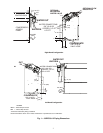
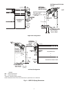
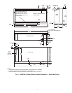
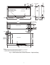
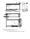
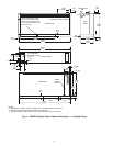
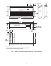
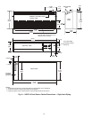
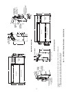
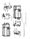
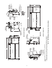
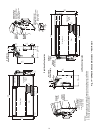
Step 1 — Check Jobsite —
Units are typically in-
stalled along an outside wall of the room. Refer to Fig. 1 and 2
for an illustration showing piping locations. Install units with
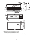
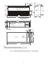
adequate clearance to allow maintenance and servicing. Refer
to Table 1 and Fig. 3-14. Locate the console unit so that it pro-
vides adequate air circulation throughout the room.
Installation, operation and maintenance instructions are
provided with each unit. Before unit start-up, read all manuals
and become familiar with the unit and its operation. Thoroughly
check out the system before operation. Complete the inspections
and instructions listed below to prepare a unit for installation.
1. Compare the electrical data on the unit nameplate with
ordering and shipping information to verify that the cor-
rect unit has been shipped.
2. Keep both the chassis and cabinet covered with the ship-
ping carton until all plastering, painting, and finish work
is complete and it is time to install the chassis and cabinet.
3. Verify that the refrigerant tubing is free of kinks or dents,
and that it does not touch other unit components.
4. Inspect all electrical connections. Connections must be
clean and tight at the terminals.
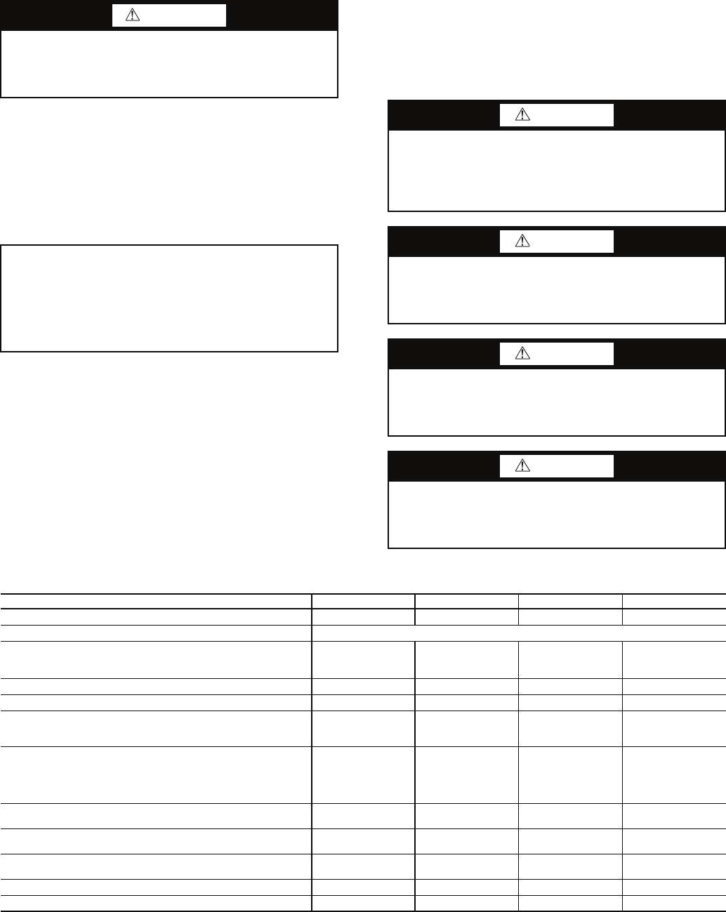
Table 1 — 50PEC Physical Data
WARNING
Electrical shock can cause personal injury or death. Before
installing or servicing system, always turn off main power
to system. There may be more than one disconnect switch.
Turn off accessory heater power if applicable.
IMPORTANT: The installation of console water source heat
pump units and all associated components, parts, and acces-
sories which make up the installation shall be in accordance
with the regulations of ALL authorities having jurisdiction
and MUST conform to all applicable codes. It is the respon-
sibility of the installing contractor to determine and comply
with ALL applicable codes and regulations.
CAUTION
To avoid equipment damage, do not use these units as a
source of heating or cooling during the construction pro-
cess. The mechanical components and filters used in these
units quickly become clogged with construction dirt and
debris which may cause system damage.
CAUTION
To avoid the release of refrigerant into the atmosphere, the
refrigerant circuit of this unit must only be serviced by
technicians who meet local, regional, and national profi-
ciency requirements.
CAUTION
All refrigerant discharged from this unit must be recovered
without exception. Technicians must follow industry
accepted guidelines and all local, regional, and national
statutes for the recovery and disposal of refrigerants.
CAUTION
When a compressor is removed from this unit, system
refrigerant circuit oil will remain in the compressor. To
avoid leakage of compressor oil, the refrigerant lines of the
compressor must be sealed after it is removed.
BASE UNIT 50PEC 09 12 15 18
NOMINAL COOLING CAPACITY (Btuh)
9,300 12,300 13,800 16,000
COMPRESSOR
Rotary
BLOWER
Motor Horsepower
Wheel Size D x W (in.) 2 each
1
/
20
5
1
/
4
x 6
1
/
4
1
/
12
5
1
/
4
x 6
1
/
4
1
/
8
5
1
/
4
x 6
1
/
4
1
/
8
5
1
/
4
x 6
1
/
4
FILTER SIZE (in.) Bottom Return (Qty)
10 x 30 x 1 (1) 10 x 30 x 1 (1) 10 x 30 x 1 (1) 10 x 36 x 1 (1)
FILTER SIZE (in.) Front Return (Qty)
7 x 29
1
/
2
x
1
/
8
(1) 7 x 29
1
/
2
x
1
/
8
(1) 7 x 29
1
/
2
x
1
/
8
(1) 7 x 35
1
/
2
x
1
/
8
(1)
UNIT WEIGHT (lb)
Shipping
Operating
185
175
190
180
200
190
232
220
REF. TO AIR HEAT EXCHANGER
Face Area (sq ft)
No. of Rows Deep
Copper Tube Size OD (in.)
Fin Spacing (FPI)
1.4
2
3
/
8
13
1.4
3
3
/
8
13
1.8
3
3
/
8
13
1.8
3
3
/
8
12
REFRIG. CHARGE (R-410A)/CKT (oz)
No. of Circuits
28
1
29
1
37
1
39
1
UNIT CABINET WITH BOTTOM RETURN WITH STANDARD
5 in. SUBBASE Width x Height x Depth (in.) 48 x 26 x 12 48 x 26 x 12 48 x 26 x 12 54 x 26 x 12
UNIT CABINET WITH FRONT RETURN
(NO SUBBASE) Width x Height x Depth (in.) 48 x 21 x 12 48 x 21 x 12 48 x 21 x 12 54 x 21 x 12
WATER IN/OUT SIZE OD SWEAT (in.)
1
/
2
1
/
2
1
/
2
3
/
4
CONDENSATE SIZE ID VINYL (in.)
5
/
8
5
/
8
5
/
8
5
/
8