


46
produce water (or debris) velocities that can erode the heat ex-
changer wall and ultimately produce leaks.
Proper water treatment can minimize tube fouling and
pitting. If such conditions are anticipated, water treatment anal-
ysis is recommended. Refer to the Carrier System Design Man-
ual, Part 5, for general water conditioning information.
Clean condensers with an inhibited hydrochloric acid solu-
tion. The acid can stain hands and clothing, damage concrete,
and, without inhibitor, damage steel. Cover surroundings to
guard against splashing. Vapors from vent pipe are not harmful,
but take care to prevent liquid from being carried over by the
gases.
Warm solution acts faster, but cold solution is just as effec-
tive if applied for a longer period.
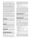
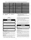
GRAVITY FLOW METHOD — Do not add solution faster
than vent can exhaust the generated gases.
When condenser is full, allow solution to remain overnight,
then drain condenser and flush with clean water. Follow acid
manufacturer’s instructions. See Fig. 37.
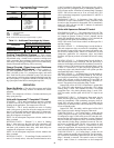
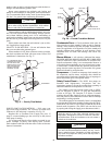
FORCED CIRCULATION METHOD — Fully open vent
pipe when filling condenser. The vent may be closed when
condenser is full and pump is operating. See Fig. 38.
Regulate flow to condenser with a supply line valve. If
pump is a nonoverloading type, the valve may be fully closed
while pump is running.
For average scale deposit, allow solution to remain in con-
denser overnight. For heavy scale deposit, allow 24 hours.
Drain condenser and flush with clean water. Follow acid manu-
facturer’s instructions.
Condensate Pans — Check condensate drain pans for
algae growth every three months. If algae growth is apparent,
consult a water treatment specialist for proper chemical treat-
ment. The application of an algaecide every three months will
typically eliminate algae problems in most locations. Check
condensate hose for leaks and blockage and correct any
problems.
Blower Motors — All units have lubricated fan motors.
BLOWER MOTORS SHOULD NEVER BE LUBRICATED
UNLESS OBVIOUS, DRY OPERATION IS SUSPECTED.
Periodic maintenance oiling is not recommended because it
will result in dirt accumulating on excess oil and cause eventu-
al motor failure. Conduct annual dry operation check and am-
perage check to ensure amp draw is no more than 10% greater
than that indicated by serial plate data.
Compressor — Conduct an amperage check annually on
the compressor and fan motor. Amperage draw should not
exceed normal full load amps. Maintain a log of amperage to
detect deterioration prior to component failure.
Safety Control Reset — The 50PEC heat pumps are
furnished with high-pressure, low-pressure and low-
temperature cutouts to prevent the machine from operating at
abnormal conditions of temperature or water flow.
The contacts of the high-pressure control used on 50PEC
units are designed to open at 376 psig and automatically
re-close at 304 psig. The Complete C or Deluxe D control
monitors this and other functions such as refrigerant tempera-
tures and pressures and condensate overflow and will interrupt
unit heating or cooling operation.
The machine must be reset manually. Reset is accomplished
by pressing the STOP button and then pushing either HI HEAT,
LOW HEAT, HI COOL or LO COOL to restart the unit in the
desired mode of operation. (The 50PEC unit can also be reset
by opening and closing the supply power disconnect switch.)
CAUTION
Follow all safety codes. Wear safety glasses and rubber
gloves when using inhibited hydrochloric acid solution.
Observe and follow acid manufacturer’s instructions.
IMPORTANT: If the unit must be reset more than twice,
check the unit for a dirty filter, abnormal entering water
temperature, inadequate or excessive water flow, and inter-
nal malfunctions. If the unit continues to cut out, contact a
trained service technician.
WARNING
When replacing the compressor contactor or lockout relay
in a unit with electromechanical controls, use only Carrier
factory authorized parts. Substitution of other components
may result in an inoperative safety circuit and may cause a
hazardous condition.
SUCTION
PUMP
SUPPORT
TANK
FINE MESH
SCREEN
RETURN
GAS VENT
PUMP
PRIMING
CONN.
GLOBE
VALVES
SUPPLY
1” PIPE
CONDENSER
REMOVE WATER
REGULATING VALVE
Fig. 38 — Forced Circulation Method
FILL CONDENSER WITH
CLEANING SOLUTION. DO
NOT ADD SOLUTION
MORE RAPIDLY THAN
VENT CAN EXHAUST
GASES CAUSED BY
CHEMICAL ACTION.
PAIL
FUNNEL
CONDENSER
PAIL
3’ TO 4’
VENT
PIPE
5’ APPROX
1”
PIPE
Fig. 37 — Gravity Flow Method